2. Peripherals and Interfaces
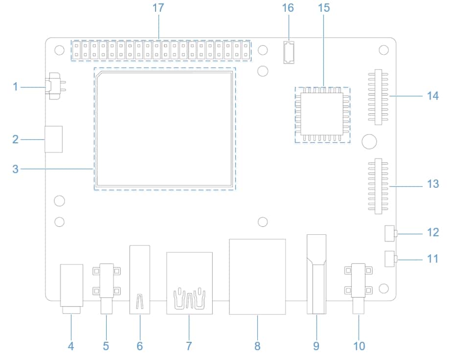
2.1 Hardware resource diagram
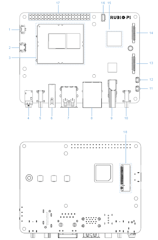
| No. | Interface | No. | Interface |
|---|---|---|---|
| 1 | RTC battery connector | 10 | Power Delivery over Type-C |
| 2 | Micro USB (UART debug) | 11 | Power-on button |
| 3 | QCS6490 module | 12 | EDL button |
| 4 | 3.5mm headphone jack | 13 | Camera connector 1 |
| 5 | USB Type-C with DP (USB3.1) | 14 | Camera connector 2 |
| 6 | USB Type-A (USB2.0) | 15 | Wi-Fi/BT module |
| 7 | 2 x USB Type-A (USB3.0) | 16 | Fan connector |
| 8 | 1000M Ethernet | 17 | 40-pin LS connector |
| 9 | HDMI OUT | 18 | M.2 Key M connector |
2.2 40-pin LS connector
2.2.1 GPIO
2.2.1.1 Pinout
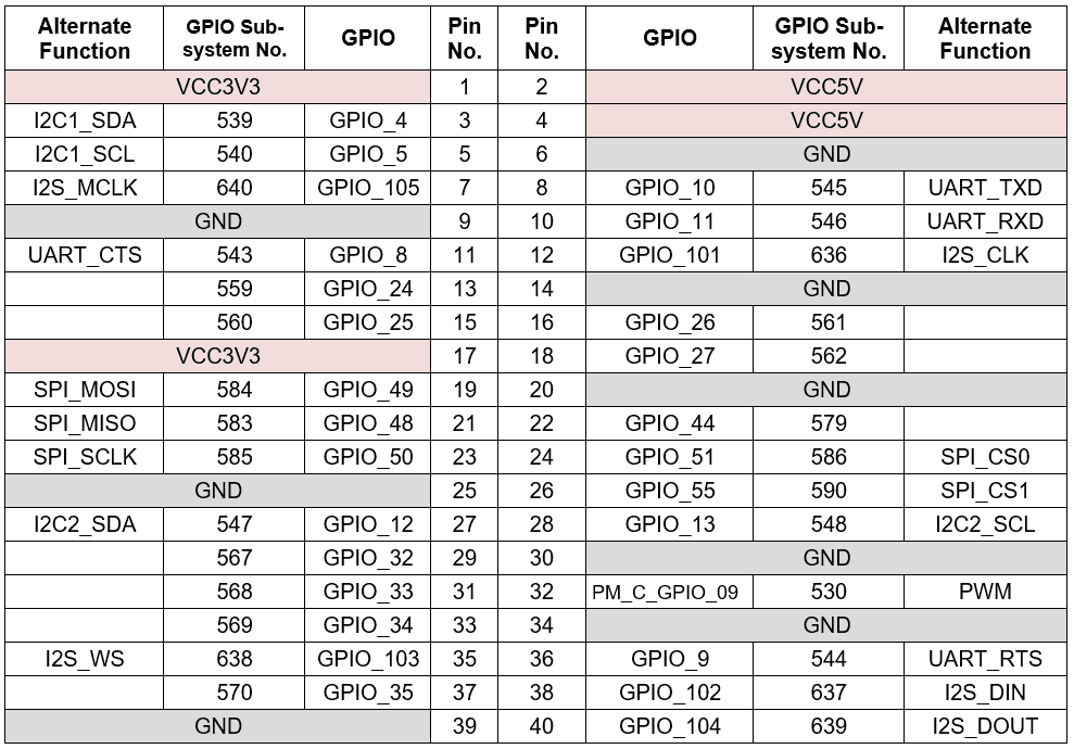
GPIO pin numbers are always required when GPIOs are used in user space. The following table lists the GPIO pin numbers and functions of the 40-pin LS connector. For example, the name of pin 13 is GPIO_24, which corresponds to number 559 in the GPIO sub-system.
2.2.1.2 Control GPIOs using shell commands on RUBIK Pi 3
Run the following commands on RUBIK Pi 3 to control GPIOs.
Go to the /sys/class/gpio directory:
cd /sys/class/gpio
Export the GPIO to be controlled. For example, pin 3 GPIO_24:
echo 559 > export
Go to the gpio559 directory to set GPIO attributes:
cd gpio559
ls

The attributes are described as follows:
-
direction:
- Input: in
- Output: out
-
value:
- Low level: 0
- High level: 1
-
edge (interrupt edge):
- Rising edge trigger: rising
- Falling edge trigger: falling
- Both-edge trigger: both
- Disabling interrupts: none
Set pin 13 to output a high level:
echo out > direction
echo 1 > value
Cancel the export of pin 13 to user space:
echo 559 > unexport
2.2.1.3 Control GPIOs using Python programs on RUBIK Pi 3
- GPIOs can be controlled by using python-periphery. Run the following command to install python-periphery on RUBIK Pi 3:
pip3 install python-periphery
- The following code snippet uses python-periphery to operate GPIOs: set pin 13 as output, pin 15 as input, and loop to check the level status of pin 15.
from periphery import GPIO
import time

out_gpio = GPIO(559, "out")
in_gpio = GPIO(560, "in")

try:
    while True:
        try:
            out_gpio.write(True)
            pin_level = in_gpio.read()
            print(f"in_gpio level: {pin_level}")

            out_gpio.write(False)
            pin_level = in_gpio.read()
            print(f"in_gpio level: {pin_level}")

            time.sleep(1)

        except KeyboardInterrupt:
            out_gpio.write(False)
            break

except IOError:
    print("Error")

finally:
    out_gpio.close()
    in_gpio.close()
- Transfer gpio.py to RUBIK Pi 3. For example, use the ADB method.
adb push gpio.py /opt
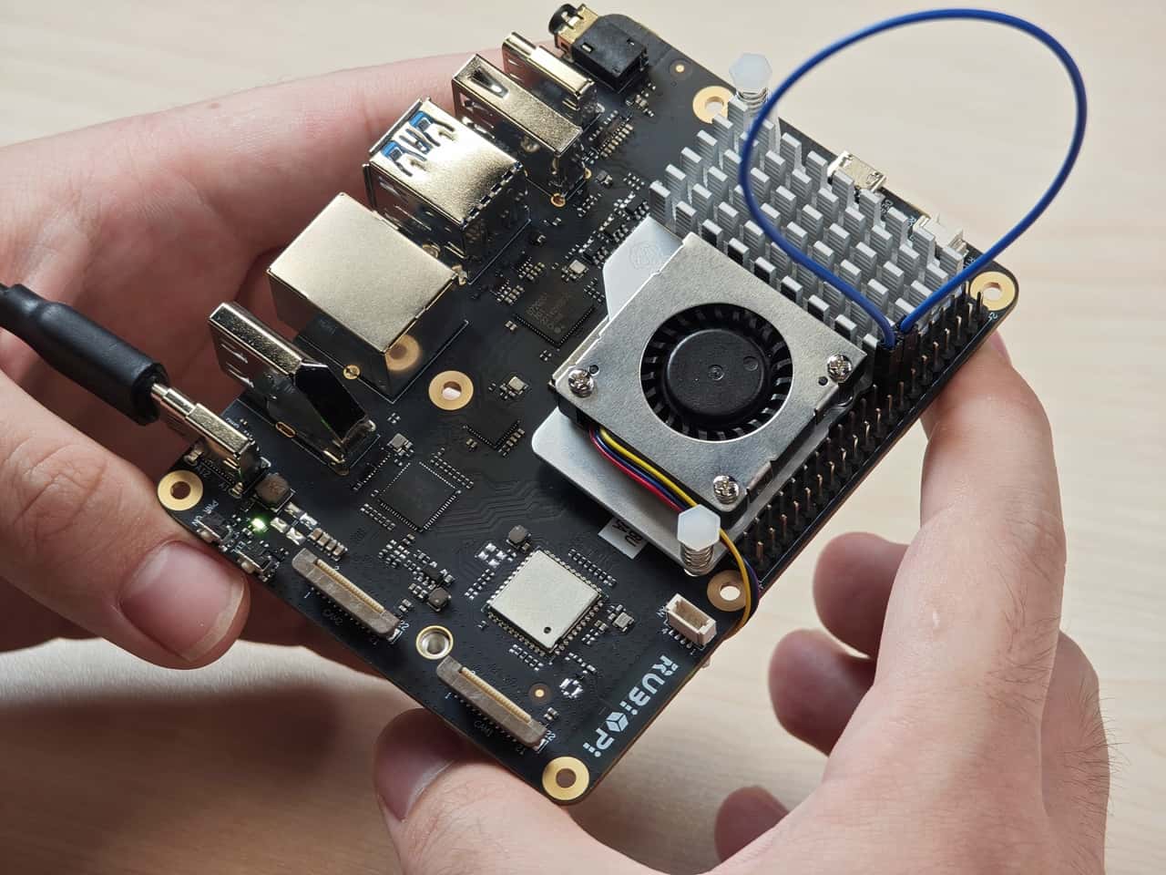
- Use the Dupont wire to short pin 13 and pin 15 as shown in the following figure to test the GPIO level control and read the level.
The program execution result is as follows:
cd /opt
python3 gpio.py
2.2.1.4 Control GPIOs using C programs
- The following code snippet sets pin 13 as output, pin 15 as input, and loops to check the level status of pin 15.
#include <stdio.h>
#include <stdlib.h>
#include <unistd.h>

int out_gpio = 559;
int in_gpio = 560;

int main() {
    char export_path[50] = {};
    char export_command[100] = {};
    snprintf(export_path, sizeof(export_path), "/sys/class/gpio/export");
    snprintf(export_command, sizeof(export_command), "echo %d > %s ", out_gpio, export_path);
    system(export_command);
    snprintf(export_command, sizeof(export_command), "echo %d > %s ", in_gpio, export_path);
    system(export_command);

    char direction_path[50] = {};
    snprintf(direction_path, sizeof(direction_path), "/sys/class/gpio/gpio%d/direction", out_gpio);
    FILE *direction_file = fopen(direction_path, "w");
    if (direction_file == NULL) {
        perror("Failed to open GPIO direction file");
        return -1;
    }
    fprintf(direction_file, "out");
    fclose(direction_file);

    snprintf(direction_path, sizeof(direction_path), "/sys/class/gpio/gpio%d/direction", in_gpio);
    direction_file = fopen(direction_path, "w");
    if (direction_file == NULL) {
        perror("Failed to open GPIO direction file");
        return -1;
    }
    fprintf(direction_file, "in");
    fclose(direction_file);

    char value_in_path[50] = {};
    char value_out_path[50] = {};
    char cat_command[100] = {};
    snprintf(value_out_path, sizeof(value_out_path), "/sys/class/gpio/gpio%d/value", out_gpio);
    snprintf(value_in_path, sizeof(value_in_path), "/sys/class/gpio/gpio%d/value", in_gpio);
    snprintf(cat_command, sizeof(cat_command), "cat %s", value_in_path);

    FILE *value_out_file = fopen(value_out_path, "w");
    if (value_out_file == NULL) {
        perror("Failed to open GPIO value file");
        return -1;
    }

    for (int i = 0; i < 5; i++) {
        fprintf(value_out_file, "1");
        fflush(value_out_file);

        system(cat_command);
        sleep(1);

        fprintf(value_out_file, "0");
        fflush(value_out_file);

        system(cat_command);
        sleep(1);
    }

    fclose(value_out_file);

    char unexport_path[50] = {};
    char unexport_command[100] = {};
    snprintf(unexport_path, sizeof(unexport_path), "/sys/class/gpio/unexport");
    snprintf(unexport_command, sizeof(unexport_command), "echo %d > %s ", out_gpio, unexport_path);
    system(unexport_command);
    snprintf(unexport_command, sizeof(unexport_command), "echo %d > %s ", in_gpio, unexport_path);
    system(unexport_command);

    return 0;
}
- Cross-compile the program. For details, refer to "1.11.3. Use the cross-compilation tools".
aarch64-qcom-linux-gcc gpio.c -o gpio --sysroot=/home/zhy/qcom_sdk_meta/sysroots/armv8-2a-qcom-linux/
- Transfer gpio to RUBIK Pi 3. For example, use the ADB method.
adb push gpio /opt
- Use the Dupont wire to short pin 13 and pin 15 as shown in the following figure to test the GPIO level control and read the level.

The program execution result is as follows:
cd /opt
./gpio
2.2.2 I2C
2.2.2.1 Pinout

Pins 3 and pin 5 are configured as I2C1 by default.
2.2.2.2 I2C communication using shell commands on RUBIK Pi 3
Run the following commands on RUBIK Pi 3 to control the I2C bus.
- View devices connected to the I2C1 interface:
i2cdetect -a -y -r 1
- Read all registers of the device whose address is 0x38:
i2cdump -f -y 3 0x38
- Write 0xaa to register 0x01 of the device whose address is 0x38:
i2cset -f -y 1 0x38 0x01 0xaa
- Read the value at register 0x01 of the device whose address is 0x38:
i2cget -f -y 1 0x38 0x01
2.2.2.3 I2C communication using Python programs
- I2C can be controlled by using the Python smbus library. Run the following command on RUBIK Pi 3 to install the library.
pip3 install smbus
- The following code snippet uses the I2C1 bus to communicate with a device whose address is 0x38: writing 0xaa to address 0x01 of the device.
import smbus

def main():
    data = [0x01, 0xaa]

    try:
        i2c_bus = smbus.SMBus(1)

        print("i2cdetect addr : ", end="")
        for address in range(0x7F):
            try:
                i2c_bus.write_i2c_block_data(address, 0, data)
                print("0x{:02X},".format(address), end="")
            except OSError:
                pass

        print()

    except Exception as e:
        print(f"An error occurred: {e}")

    finally:
        if i2c_bus:
            i2c_bus.close()

if __name__ == "__main__":
    main()
- Transfer i2c.py to RUBUK Pi 3. For example, use the ADB method.
adb push i2c.py /opt
- Connect pin 3 and pin 5 to the I2C sensor and test the I2C communication as shown in the following figure.
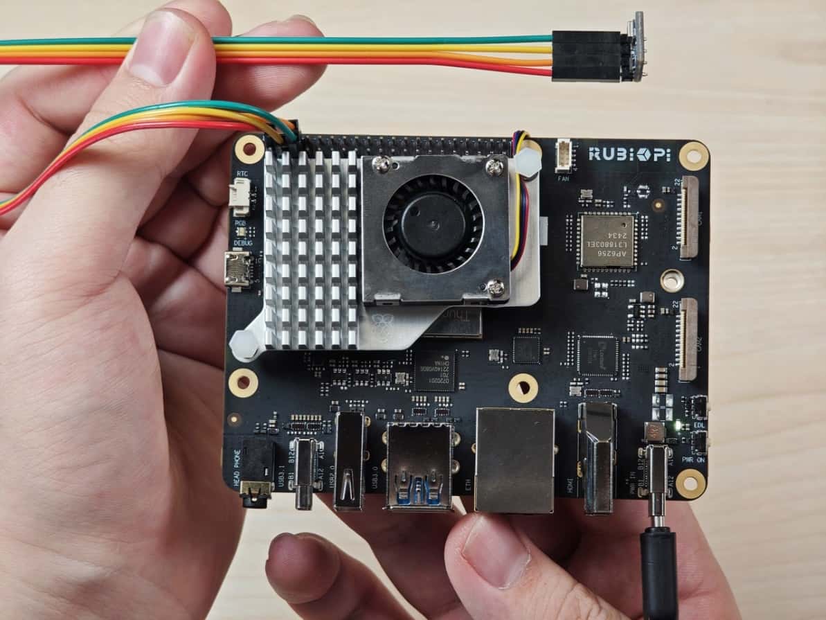
cd /opt
python3 i2c.py
The program execution result is as follows:
2.2.2.4 I2C communication using C programs
- The following code snippet uses the I2C1 bus to communicate with a device whose address is 0x38: writing 0xaa to address 0x01 of the device.
#include <stdio.h>
#include <stdlib.h>
#include <stdint.h>
#include <fcntl.h>
#include <unistd.h>
#include <linux/i2c-dev.h>
#include <sys/ioctl.h>

#define I2C_DEVICE_PATH "/dev/i2c-1"

int main() {
    uint8_t data[2] = {0x01,0xaa};

    const char *i2c_device = I2C_DEVICE_PATH;
    int i2c_file;

    if ((i2c_file = open(i2c_device, O_RDWR)) < 0) {
        perror("Failed to open I2C device");
        return -1;
    }

    ioctl(i2c_file, I2C_TENBIT, 0);
    ioctl(i2c_file, I2C_RETRIES, 5);

    printf("i2cdetect addr : ");
    for (int x = 0; x < 0x7f; x++)
    {
        if (ioctl(i2c_file, I2C_SLAVE, x) < 0) {
            perror("Failed to set I2C slave address");
            close(i2c_file);
            return -1;
        }

        if (write(i2c_file, data, 2) == 2)
        {
            printf("0x%x,", x);
        }
    }

    close(i2c_file);
    printf("\r\n");

    return 0;
}
- Cross-compile the program. For details, refer to "1.11.3. Use the cross-compilation tools".
aarch64-qcom-linux-gcc i2c.c -o i2c --sysroot=/home/zhy/qcom_sdk_meta/sysroots/armv8-2a-qcom-linux/
- Transfer i2c to RUBIK Pi 3. For example, use the ADB method.
adb push i2c /opt
- Connect pin 3 and pin 5 to the I2C sensor to test the I2C bus communication as shown in the following figure.
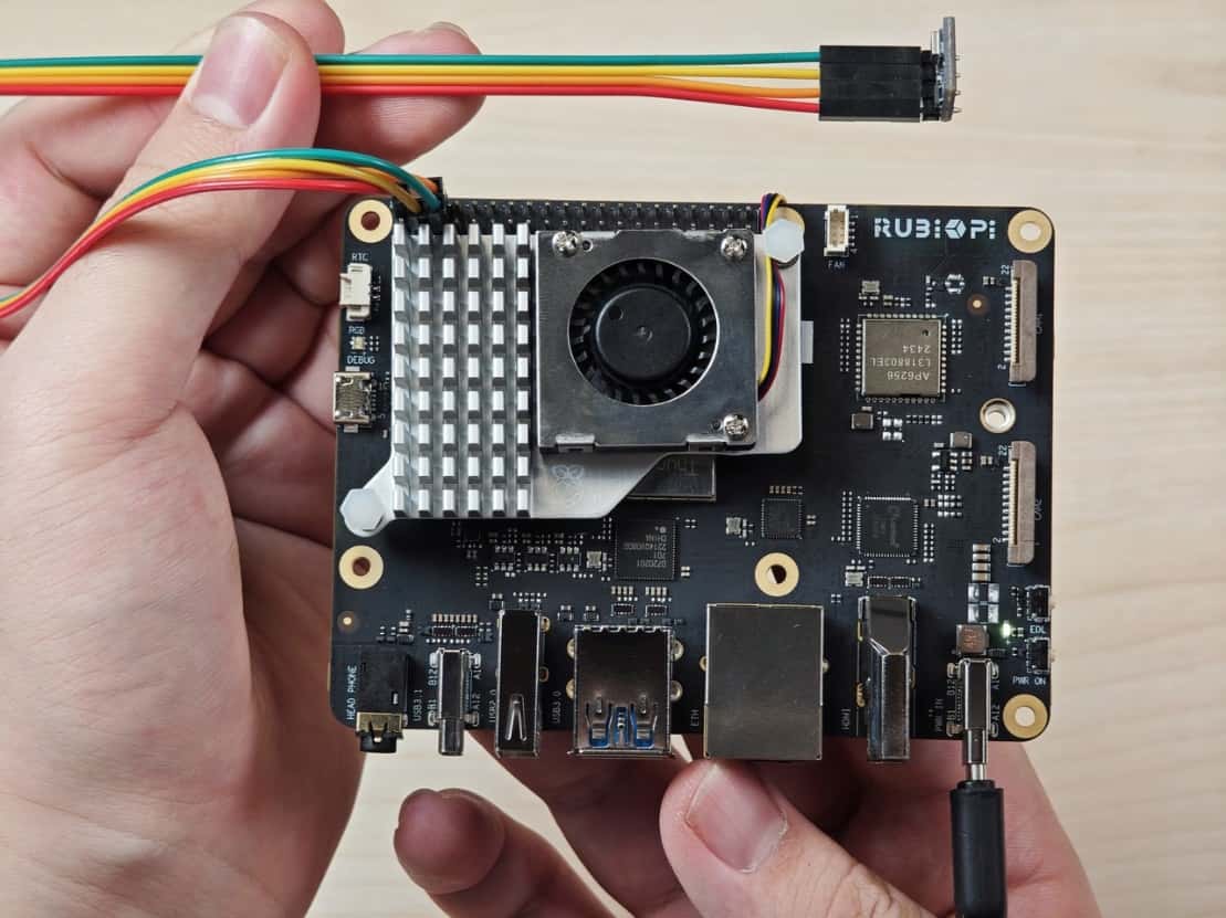
cd /opt
./i2c
The program execution result is as follows:
2.2.3 SPI
2.2.3.1 Pinout

Pins 19, 21, 23, and 24 are set as SPI by default.
2.2.3.2 SPI communication using Python programs
- SPI communication can be implemented by using the spidev library for Python. Run the following command to install spidev on RUBIK Pi 3.
pip3 install spidev
- The following code snippet uses the SPI bus to send and receive data.
import spidev

def main():
    tx_buffer = [ord(char) for char in "hello world!"]
    rx_buffer = [0] * len(tx_buffer)

    try:
        spi = spidev.SpiDev()
        spi.open(12, 0)
        spi.max_speed_hz = 1000000

        rx_buffer = spi.xfer2(tx_buffer[:])
        print("tx_buffer:\n\r", ''.join(map(chr, tx_buffer)))
        print("rx_buffer:\n\r", ''.join(map(chr, rx_buffer)))

    except Exception as e:
        print(f"An error occurred: {e}")

    finally:
        if spi:
            spi.close()

if __name__ == "__main__":
    main()
- Transfer spi.py to RUBIK Pi 3. For example, use the ADB method.
adb push spi.py /opt
- Short pin 19 and pin 21 with a Dupont wire to test the SPI bus communication as shown in the following figure.

The program execution result is as follows:
python3 spi.py
2.2.3.3 SPI communication using C programs
- The following code snippet uses the SPI bus to send and receive data.
#include <stdio.h>
#include <stdlib.h>
#include <stdint.h>
#include <fcntl.h>
#include <unistd.h>
#include <linux/spi/spidev.h>
#include <sys/ioctl.h>

#define SPI_DEVICE_PATH "/dev/spidev12.0"

int main() {
    int spi_file;
    uint8_t tx_buffer[50] = "hello world!";
    uint8_t rx_buffer[50];

    // Open the SPI device
    if ((spi_file = open(SPI_DEVICE_PATH, O_RDWR)) < 0) {
        perror("Failed to open SPI device");
        return -1;
    }

    // Configure SPI mode and bits per word
    uint8_t mode = SPI_MODE_0;
    uint8_t bits = 8;
    if (ioctl(spi_file, SPI_IOC_WR_MODE, &mode) < 0) {
        perror("Failed to set SPI mode");
        close(spi_file);
        return -1;
    }
    if (ioctl(spi_file, SPI_IOC_WR_BITS_PER_WORD, &bits) < 0) {
        perror("Failed to set SPI bits per word");
        close(spi_file);
        return -1;
    }

    // Perform SPI transfer
    struct spi_ioc_transfer transfer = {
        .tx_buf = (unsigned long)tx_buffer,
        .rx_buf = (unsigned long)rx_buffer,
        .len = sizeof(tx_buffer),
        .delay_usecs = 0,
        .speed_hz = 1000000,  // SPI speed in Hz
        .bits_per_word = 8,
    };

    if (ioctl(spi_file, SPI_IOC_MESSAGE(1), &transfer) < 0) {
        perror("Failed to perform SPI transfer");
        close(spi_file);
        return -1;
    }

     /* Print tx_buffer and rx_buffer*/
    printf("\rtx_buffer: \n %s\n ", tx_buffer);
    printf("\rrx_buffer: \n %s\n ", rx_buffer);

    // Close the SPI device
    close(spi_file);

    return 0;
}
- Cross-compile the program. For details, refer to "1.11.3. Use the cross-compilation tools".
aarch64-qcom-linux-gcc spi.c -o spi --sysroot=/home/zhy/qcom_sdk_meta/sysroots/armv8-2a-qcom-linux/
- Transfer spi to RUBIK Pi 3. For example, use the ADB method.
adb push spi /opt
- Short pin 19 and pin 21 with a Dupont wire to test the SPI bus communication as shown in the following figure.

The program execution result is as follows:
cd /opt
./spi
2.2.4 UART
2.2.4.1 Pinout
Pins 8 and 10 have been configured as UART by default. The device node is /dev/ttyHS3.
2.2.4.2 UART communication using shell commands on RUBIK Pi 3
Run the following commands on RUBIK Pi 3 to control UART communication.
- Use the stty tool to configure UART. Run the following commands to set both the input rate and output rate of UART to 115200 and disable the echo.
    stty -F /dev/ttyHS3 ispeed 115200 ospeed 115200
    stty -F /dev/ttyHS3 -echo
- Enable the two terminals on RUBIK Pi 3, short pin 8 and pin 10 with a Dupont wire, and run the following commands. The content sent by the transmitter will be displayed on the receiver.
    echo "hello world!" > /dev/ttyHS3 #Transmitter
    cat /dev/ttyHS3 #Receiver
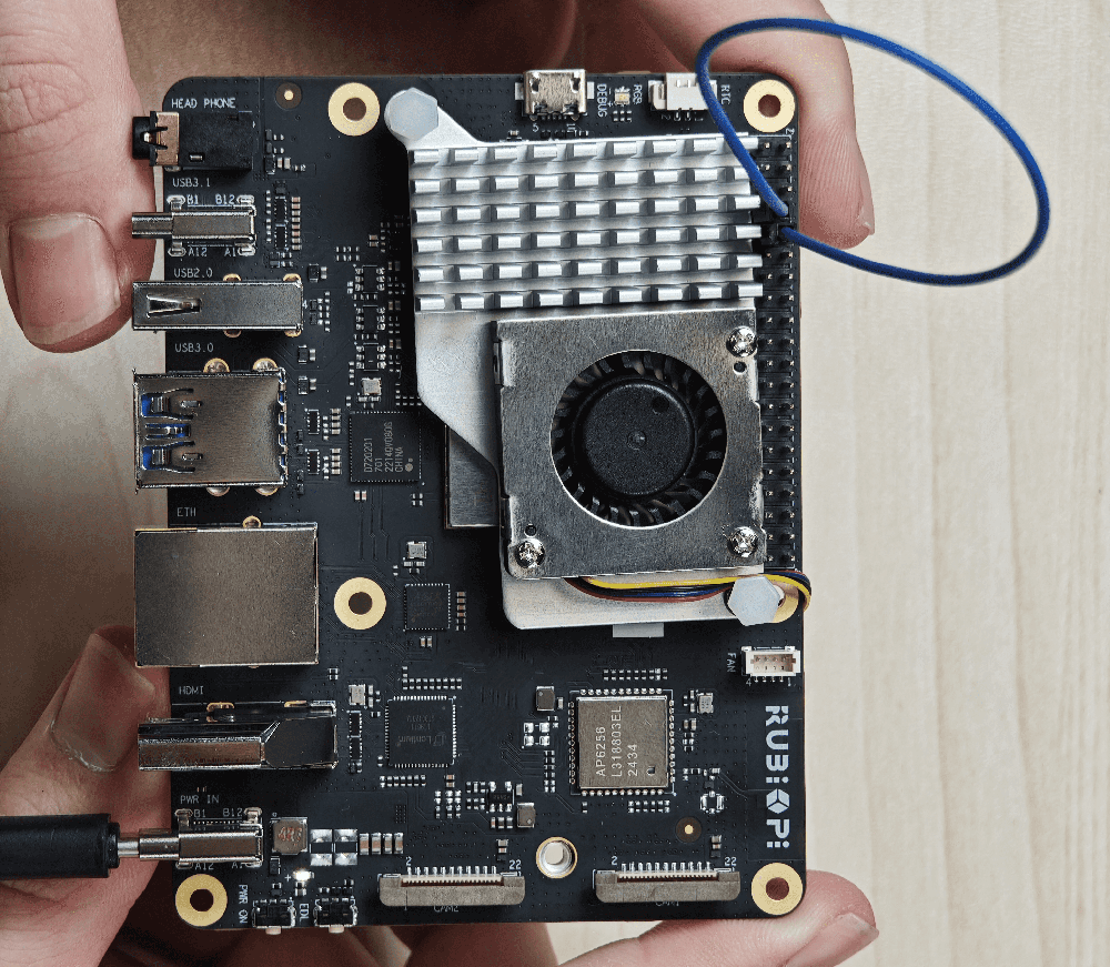
2.2.4.3 UART communication using Python programs
- UART communication can be implemented by using the serial library for Python. Run the following command to install the serial library on RUBIK Pi 3.
pip3 install pyserial
- Create the uart.py file and use UART to send and receive data.
import serial
import time

with serial.Serial(
    "/dev/ttyHS3",
    baudrate=115200,
    bytesize=serial.EIGHTBITS,
    stopbits=serial.STOPBITS_ONE,
    parity=serial.PARITY_NONE,
    timeout=1,
) as uart3:
    uart3.write(b"Hello World!\n")
    buf = uart3.read(128)
    print("Raw data:\n", buf)
    data_strings = buf.decode("utf-8")
    print("Read {:d} bytes, printed as string:\n {:s}".format(len(buf), data_strings))
- Transfer uart.py to RUBIK Pi 3. For example, use the ADB method. The command is as follows:
adb push uart.py /opt
- Short pin 8 and pin 10 with a Dupont wire to test the UART communication as shown in the following figure.

The program execution result is as follows:
python3 uart.py
2.2.4.4 UART communication using C programs
- Create the uart.c file and use UART to send and receive data.
#include <stdio.h>
#include <stdlib.h>
#include <string.h>
#include <fcntl.h>
#include <termios.h>
#include <unistd.h>

int main() {
    int serial_port_num = 3;
    char serial_port[15];

    sprintf(serial_port,"/dev/ttyHS%d",serial_port_num);
    int serial_fd;

    serial_fd = open(serial_port, O_RDWR | O_NOCTTY);
    if (serial_fd == -1) {
        perror("Failed to open serial port");
        return 1;
    }

    struct termios tty;
    memset(&tty, 0, sizeof(tty));

    if (tcgetattr(serial_fd, &tty) != 0) {
        perror("Error from tcgetattr");
        return 1;
    }

    cfsetospeed(&tty, B9600);
    cfsetispeed(&tty, B9600);

    tty.c_cflag &= ~PARENB;
    tty.c_cflag &= ~CSTOPB;
    tty.c_cflag &= ~CSIZE;
    tty.c_cflag |= CS8;

    if (tcsetattr(serial_fd, TCSANOW, &tty) != 0) {
        perror("Error from tcsetattr");
        return 1;
    }

    char tx_buffer[] = "hello world!\n";
    ssize_t bytes_written = write(serial_fd, tx_buffer, sizeof(tx_buffer));
    if (bytes_written < 0) {
        perror("Error writing to serial port");
        close(serial_fd);
        return 1;
    }
    printf("\rtx_buffer: \n %s ", tx_buffer);

    char rx_buffer[256];
    int bytes_read = read(serial_fd, rx_buffer, sizeof(rx_buffer));
    if (bytes_read > 0) {
        rx_buffer[bytes_read] = '\0';
        printf("\rrx_buffer: \n %s ", rx_buffer);
    } else {
        printf("No data received.\n");
    }

    close(serial_fd);

    return 0;
}
- Cross-compile the program. For details, refer to "1.11.3. Use the cross-compilation tools".
aarch64-qcom-linux-gcc uart.c -o uart --sysroot=/home/zhy/qcom_sdk_meta/sysroots/armv8-2a-qcom-linux/
- Transfer uart to RUBIK Pi 3. For example, use the ADB method.
adb push uart /opt
- Short pin 8 and pin 10 with a Dupont wire and test the UART communication as shown in the following figure.

The program execution result is as follows:
cd /opt
./uart
2.3 USB
RUBIK Pi 3 provides four USB ports:
- 2 x USB 3.0, host mode only (No.7 in the following figure)
- 1 x USB 2.0, host or device mode (No. 6 in the following figure)
- 1 x USB 3.1 Gen 1, host or device mode, Type-C with DisplayPort v1.4 (No. 5 in the following figure)
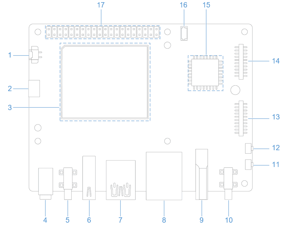
2.3.1 USB2.0
To switch the USB 2.0 port to device mode, run commands manually. The following example shows a test method. Running the following commands on RUBIK Pi 3 simulates RUBIK Pi 3 as a USB flash drive.
cd /sys/kernel/config/usb_gadget/ #Log in from the serial port and run the following command
mkdir g1
cd g1
mkdir functions/mass_storage.0

dd if=/dev/zero of=/tmp/test.iso bs=1M count=2048 #Create a 2 GB USB drive space
mkfs.ext4 /tmp/test.iso
echo "/tmp/test.iso" > functions/mass_storage.0/lun.0/file
mkdir configs/c.1
ln -s functions/mass_storage.0/ configs/c.1/f3
mount -t debugfs none /sys/kernel/debug/

echo device > /sys/kernel/debug/usb/8c00000.usb/qcom_usb2_0_mode #Switch USB to device mode
echo 8c00000.usb > UDC #Connect the USB cable. The USB drive is identified and can be written to and read from

echo host > /sys/kernel/debug/usb/8c00000.usb/qcom_usb2_0_mode #Remove the USB cable and switch to host mode
2.3.2 Type-C port
The Type-C port can automatically switch between host and device modes.
- Automatically switches to device mode when connected to PC
- Automatically switches to host mode when an OTG cable is connected
- Automatically outputs DP video signals when connected to a DP monitor
2.4 CSI
Currently, RUBIK Pi 3 is compatible with three Raspberry Pi cameras:
-
Raspberry Pi High Quality Camera (IMX477/M12 Mount)
https://www.raspberrypi.com/products/raspberry-pi-high-quality-camera/
noteIn the demonstration in Chapter 4. Qualcomm IM SDK, the IMX477 camera uses the WS1053516 lens.

-
Raspberry Pi Camera Module 2 (IMX219)
https://www.raspberrypi.com/products/camera-module-v2/
noteCurrently, the RUBIK Pi 3 only supports the standard Camera Module 2 and does not support the wide-angle or NoIR versions.
-
Raspberry Pi Camera Module 3 (IMX708)
https://www.raspberrypi.com/products/camera-module-3/
noteCurrently, the RUBIK Pi 3 only supports the standard Camera Module 3 and does not support the wide-angle or NoIR versions. The current software version does not support the autofocus (AF) function of the Module 3 camera.
2.4.1 Connect the camera cable
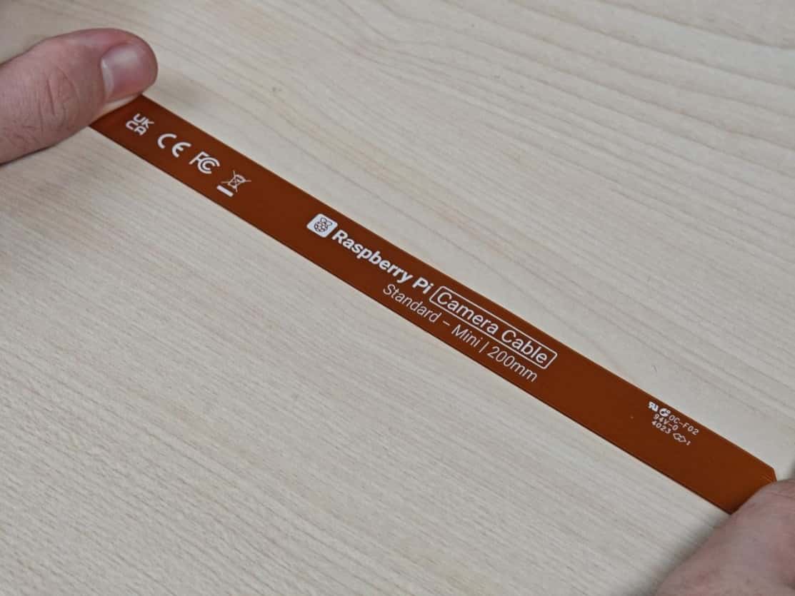
https://www.raspberrypi.com/products/camera-cable/
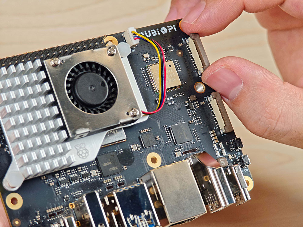
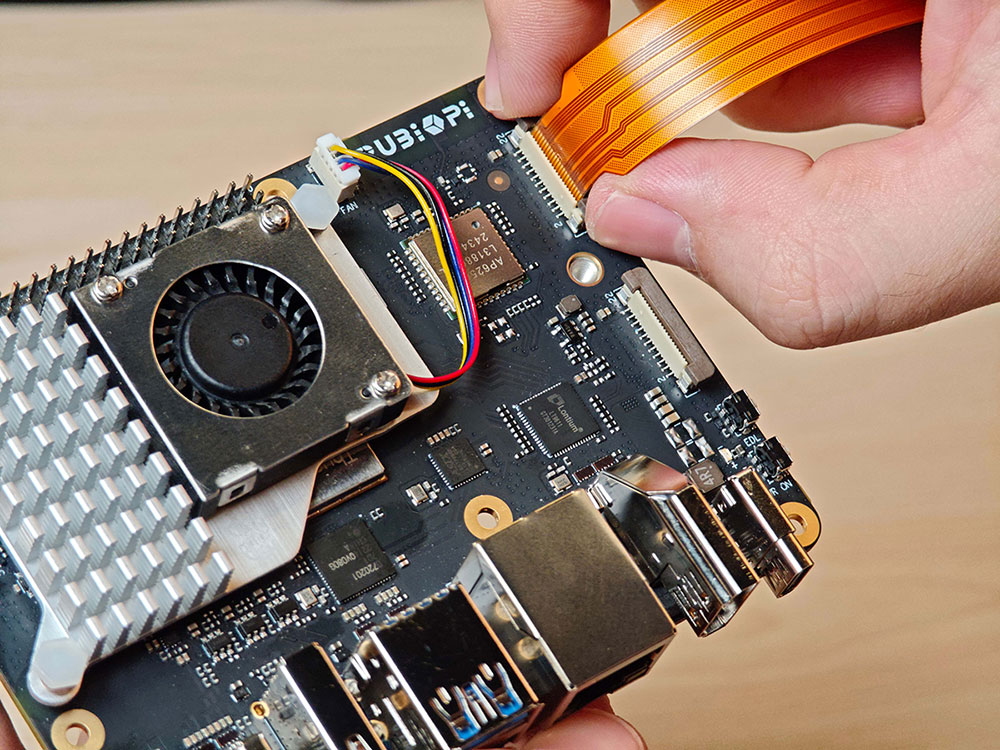
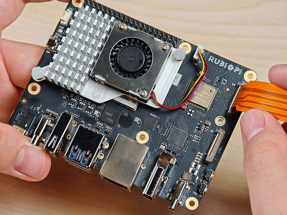
RUBIK Pi 3 supports the 22-pin FPC with a 0.5mm pitch and a 0.3±0.05mm thickness. It is compatible with the Raspberry Pi 5 FPC of the same specification.
- Pull up the lock of the connector.
- Insert the FPC. Ensure that the contact side is toward RUBIK Pi.
- Press the lock and ensure that the FPC is properly connected.
2.4.2 Use cameras
The camera can be operated by using the GStreamer command on RUBIK Pi 3. Before operation, run the following commands to set the camera.
mount -o remount,rw /
echo multiCameraLogicalXMLFile=kodiak_dc.xml > /var/cache/camera/camxoverridesettings.txt
echo enableNCSService=FALSE >> /var/cache/camera/camxoverridesettings.txt
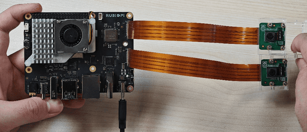
Connect cameras to connectors 13 and 14, and connect the HDMI cable, as marked in the following figure.

The following picture shows the physical connection:
- Run the following commands on RUBIK Pi 3 for the full-screen preview of a single camera:
    export XDG_RUNTIME_DIR=/dev/socket/weston
    export WAYLAND_DISPLAY=wayland-1
    setprop persist.overlay.use_c2d_blit 2
    gst-launch-1.0 -e qtiqmmfsrc camera=0 name=camsrc ! video/x-raw\(memory:GBM\),format=NV12,width=1920,height=1080,framerate=30/1,compression=ubwc ! queue ! waylandsink fullscreen=true async=true
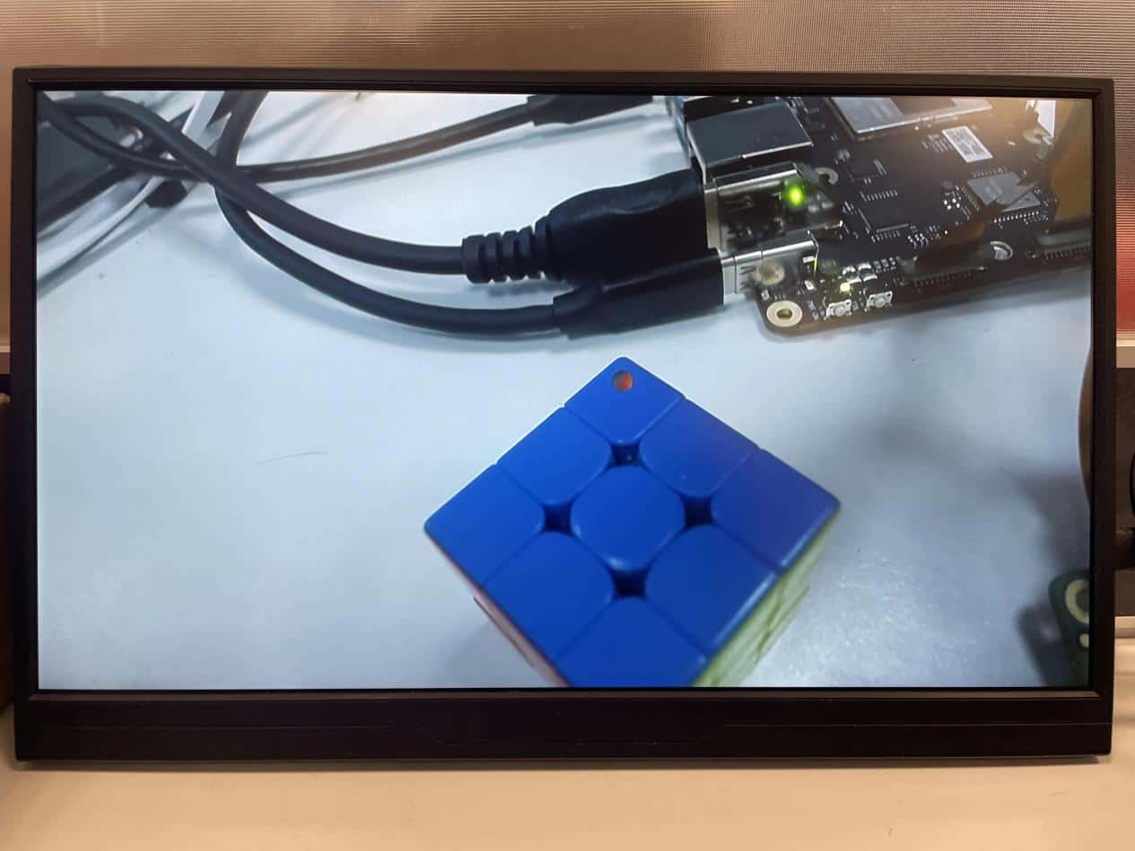
The following figure shows the preview result:
- Run the following commands on RUBIK Pi 3 for concurrent preview of two cameras:
    #Terminal 1
    export XDG_RUNTIME_DIR=/dev/socket/weston
    export WAYLAND_DISPLAY=wayland-1
    setprop persist.overlay.use_c2d_blit 2
    gst-launch-1.0 -e qtiqmmfsrc camera=0 name=camsrc ! video/x-raw\(memory:GBM\),format=NV12,width=1920,height=1080,framerate=30/1,compression=ubwc ! queue ! waylandsink sync=false x=0 y=0 width=960 height=540 enable-last-sample=false

    #Terminal 2
    export XDG_RUNTIME_DIR=/dev/socket/weston
    export WAYLAND_DISPLAY=wayland-1
    setprop persist.overlay.use_c2d_blit 2
    gst-launch-1.0 -e qtiqmmfsrc camera=1 name=camsrc ! video/x-raw\(memory:GBM\),format=NV12,width=1920,height=1080,framerate=30/1,compression=ubwc ! queue ! waylandsink sync=false x=960 y=540 width=960 height=540 enable-last-sample=false
The following figure shows the preview result:

- Run the following commands on RUBIK Pi 3 for concurrent video recording from both cameras.
    #Terminal 1:
    echo multiCameraLogicalXMLFile=kodiak_dc.xml > /var/cache/camera/camxoverridesettings.txt
    export XDG_RUNTIME_DIR=/dev/socket/weston
    export WAYLAND_DISPLAY=wayland-1
    setprop persist.overlay.use_c2d_blit 2
    gst-launch-1.0 -e qtiqmmfsrc camera=0 name=camsrc video_0::type=preview ! video/x-raw\(memory:GBM\),format=NV12,width=1920,height=1080,framerate=30/1,compression=ubwc,interlace-mode=progressive,colorimetry=bt601 ! queue ! v4l2h264enc capture-io-mode=5 output-io-mode=5 ! queue ! h264parse ! mp4mux ! queue ! filesink location="/opt/mux0.mp4"

    #Terminal 2:
    export XDG_RUNTIME_DIR=/dev/socket/weston
    export WAYLAND_DISPLAY=wayland-1
    setprop persist.overlay.use_c2d_blit 2
    gst-launch-1.0 -e qtiqmmfsrc camera=1 name=camsrc video_0::type=preview ! video/x-raw\(memory:GBM\),format=NV12,width=1920,height=1080,framerate=30/1,compression=ubwc,interlace-mode=progressive,colorimetry=bt601 ! queue ! v4l2h264enc capture-io-mode=5 output-io-mode=5 ! queue ! h264parse ! mp4mux ! queue ! filesink location="/opt/mux1.mp4"
The recorded video files are saved in the /opt directory.
- Run the following commands on RUBIK Pi 3 for concurrent preview and video recording from two cameras.
    #Terminal 1
    export XDG_RUNTIME_DIR=/dev/socket/weston
    export WAYLAND_DISPLAY=wayland-1
    setprop persist.overlay.use_c2d_blit 2
    gst-launch-1.0 -e qtiqmmfsrc camera=0 name=camsrc video_0::type=preview ! video/x-raw\(memory:GBM\),format=NV12,width=1920,height=1080,framerate=30/1,compression=ubwc,interlace-mode=progressive,colorimetry=bt601 ! queue ! v4l2h264enc capture-io-mode=5 output-io-mode=5 ! queue ! h264parse ! mp4mux ! queue ! filesink location="/opt/mux0.mp4" camsrc. ! video/x-raw\(memory:GBM\),format=NV12,width=1920,height=1080,framerate=30/1,compression=ubwc ! waylandsink sync=false x=0 y=0 width=960 height=540 enable-last-sample=false

    #Terminal 2
    export XDG_RUNTIME_DIR=/dev/socket/weston
    export WAYLAND_DISPLAY=wayland-1
    setprop persist.overlay.use_c2d_blit 2
    gst-launch-1.0 -e qtiqmmfsrc camera=1 name=camsrc video_0::type=preview ! video/x-raw\(memory:GBM\),format=NV12,width=1920,height=1080,framerate=30/1,compression=ubwc,interlace-mode=progressive,colorimetry=bt601 ! queue ! v4l2h264enc capture-io-mode=5 output-io-mode=5 ! queue ! h264parse ! mp4mux ! queue ! filesink location="/opt/mux1.mp4" camsrc. ! video/x-raw\(memory:GBM\),format=NV12,width=1920,height=1080,framerate=30/1,compression=ubwc ! waylandsink sync=false x=960 y=540 width=960 height=540 enable-last-sample=false
The recorded video files are saved in the /opt directory.
The following figure shows the preview result:

2.5 HDMI OUT
The HDMI connector is component No.9 in the following figure. RUBIK Pi 3 supports HDMI 1.4 and a maximum output of 4K 30 Hz. It also supports the CEC functionality, resolution adaptation (output at the highest resolution supported by the screen), and hot-swapping.

2.5.1 CEC
HDMI Consumer Electronics Control (CEC) is a feature of HDMI designed to interconnect and control multiple connected devices via a single HDMI cable. CEC facilitates communication between connected devices through a dedicated CEC pin. For example, multiple devices can be controlled with a single remote control.
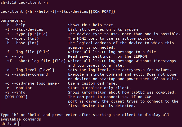
RUBIK Pi 3 integrates the cec-client tool. After connecting the HDMI cable to a TV, run the following command to check whether the TV supports CEC.
echo 'scan' | cec-client -s -d 1
If the TV supports CEC, the following output will be returned:
opening a connection to the CEC adapter...
requesting CEC bus information ...
CEC bus information
===================
device #0: TV
address:       0.0.0.0
active source: no
vendor:        Sony
osd string:    TV
CEC version:   1.4
power status:  standby
language:      eng


device #1: Recorder 1
address:       1.0.0.0
active source: no
vendor:        Pulse Eight
osd string:    CECTester
CEC version:   1.4
power status:  on
language:      eng


device #4: Playback 1
address:       3.0.0.0
active source: no
vendor:        Sony
osd string:    PlayStation 4
CEC version:   1.3a
power status:  standby
language:      ???
If the TV supports the CEC function, run the following commands on RUBIK Pi 3 to increase or decrease the TV volume.
echo 'volup' | cec-client -t p -s
echo 'voldown' | cec-client -t p -s
For more information about how to use cec-client, use the -h parameter.
2.5.2 HDMI OUT touchscreen
RUBIK Pi 3 supports HDMI OUT touchscreen with 1024 x 600P resolution by default and supports the touch function as shown in the following figure:
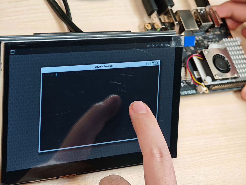
The screen used in the picture above is a 7" IPS HD touch screen.
2.6 Wi-Fi and Bluetooth
RUBIK Pi 3 is equipped with the AP6256 Wi-Fi module and supports Wi-Fi 5 and Bluetooth 5.2.
2.6.1 Wi-Fi
2.6.1.1 STA mode
In Station (STA) mode, the device can be connected to an existing Wi-Fi network to access network resources or the Internet. Run the following commands on RUBIK Pi 3:
- Scan for nearby Wi-Fi.
iw wlan0 scan | grep SSID
- Connect to Wi-Fi.
   wpa_passphrase <ssid> <passphrase> > /etc/wpa_supplicant.conf #Enter the Wi-Fi account and password

   systemctl restart wifi #Connect to Wi-Fi
The device will automatically connect to Wi-Fi the next time it is started.
- If you want to switch to another Wi-Fi network, modify the /etc/wpa_supplicant.conf file. The following example shows a modification method:
   ctrl_interface=/var/run/wpa_supplicant
   update_config=1
   pmf=1
   network={
    ssid="RUBIKPi"
    psk="123456789"
   }
- ssid is the Wi-Fi network name.
- psk is the Wi-Fi network password.
Modify the .conf file based on your actual situation.
- After modifying the configuration, run the following commands to connect to the Wi-Fi network.
    killall -9 wpa_supplicant
    wpa_supplicant -Dnl80211 -iwlan0 -c/etc/wpa_supplicant.conf -B
2.6.1.2 AP mode
In Access Point (AP) mode, the device becomes a gateway for other devices to connect to a network. The steps to create an AP are as follows:
-
Enable the AP.
1.Create or modify the /opt/hostapd.conf file:
   ctrl_interface=/var/run/hostapd
   driver=nl80211
   ieee80211n=1
   interface=wlan1
   hw_mode=a
   channel=36
   beacon_int=100
   dtim_period=1
   ssid=RUBIKPi
   auth_algs=1
   ap_isolate=0
   ignore_broadcast_ssid=0
   wpa=2
   wpa_key_mgmt=WPA-PSK
   rsn_pairwise=CCMP
   wpa_passphrase=123456789
- Run the following commands to enable the AP:
    killall wpa_supplicant
    killall dhcpcd
    ifconfig wlan1 down
    ifconfig wlan1 192.168.43.1 netmask 255.255.255.0 up
    pkill -9 dnsmasq
    dnsmasq -i wlan1 --dhcp-range=192.168.43.10,192.168.43.100
    hostapd /opt/hostapd.conf &
- Disable the AP:
    hostapd_cli disable
    killall -9 hostapd
    ifconfig wlan1 down
2.6.2 BT
Run the following commands on RUBIK Pi 3 to test the Bluetooth function.
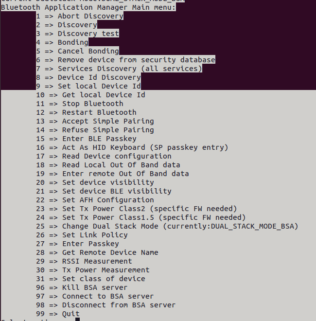
- Run the app_manager program to pair devices:
    cd /usr/src/rubikpi-bt-demo/
    ./app_manager
-
In the terminal, type "2", press Enter, and wait for the Bluetooth scan result.
-
In the terminal, type "4", press Enter, type the dev number of the Bluetooth device to be paired, and press Enter again.
-
In the terminal, type "13" as prompted to accept the pairing. The Bluetooth device to be paired also needs to accept the pairing request.
app_manager must be running at all times. Run the
adb shellcommand to create a terminal and perform the following steps.
-
Transmission via Bluetooth.
Take sending a file as an example:
    cd /usr/src/rubikpi-bt-demo/
    touch ./test_file.txt
    echo RUBIKPi > test_file.txt
    ./app_opc
    #Type 4 and press Enter
    #Type 0 and press Enter
    #Type the dev number and press Enter
    #Phone receives file
    #Type 9 and press Enter to quit
- Reception via Bluetooth
    cd /usr/src/rubikpi-bt-demo/
    mkdir push
    ./app_ops
    #Type 1 and press Enter
    #Phone sends file via Bluetooth
    #After transmission, type 9 and press Enter to quit. The transmitted file is located in the ./push folder
-
Other demos
All the BT related source code is stored in the following directory of RUBIK Pi 3:*
/usr/src/rubikpi-bt-demo/3rdparty/3rdparty/embedded/bsa_examples/linux*. Compile and view the code as needed. The following example shows the compilation method:
    cd /usr/src/rubikpi-bt-demo/3rdparty/3rdparty/embedded/bsa_examples/linux/<test demo>/build/
    export ARMGCC=gcc
    make CPU=arm64
    cp arm64/<demo executable file> /usr/src/rubikpi-bt-demo/
    cd /usr/src/rubikpi-bt-demo/
    #Run the demo
2.7 Audio
RUBIK Pi 3 supports the following audio interfaces:
- 3.5mm headphone (No. 4 in the following figure)
- HDMI OUT (No. 9 in the following figure)
- Bluetooth
2.7.1 View the sound card information
- Run the following command on RUBIK Pi 3 to view the mounted sound cards:
cat /proc/asound/cards
- Run the following command on RUBIK Pi 3 to view the list of allocated Pulse-Code Modulation (PCM) streams:
cat /proc/asound/pcm

2.7.2 Set the audio output device
Run the following commands on RUBIK Pi 3 to change the audio output source for commands such as gstreamer and paplay:
- Set the 3.5mm headphone jack as the output interface:
pactl set-sink-port 0 headset
- Set the HDMI as the output interface:
pactl set-sink-port 0 hdmi
2.7.3 Playback
- Run the following command on RUBIK Pi 3 to test headphone playback, put the test audio in the /opt directory and run the following command to play the test audio:
gst-launch-1.0 filesrc location=/opt/test.mp3 ! mpegaudioparse ! mpg123audiodec ! pulsesink
- Run the following command on RUBIK Pi 3 to test HDMI OUT playback, put the test audio in the /opt directory and run the following commands to play the test audio:
   systemctl stop pulseaudio
   agmplay /opt/test.wav -D 100 -d 100 -r 48000 -b 16 -c 2 -i MI2S-LPAIF_RXTX-RX-PRIMARY
   systemctl start pulseaudio
-
Run the following command on RUBIK Pi 3 to test Bluetooth playback, enable two terminals.
- Enable terminal 1:
cd /usr/src/rubikpi-bt-demo/
./app_manager- Enable terminal 2:
    cd /usr/src/rubikpi-bt-demo/
    ./app_av
a. Type "2" and press Enter. Wait for the Bluetooth headphone to be found.
b. Type "6" and press Enter to start establishing a connection.
c. Type "1" and press Enter to connect a recently scanned device.
d. Type the dev number of the Bluetooth device you want to connect.
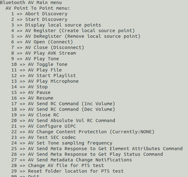
- Return to Terminal 1 and type "13" to accept the pairing.
- Return to Terminal 2, type "11", and press Enter. Select the number of the piece of music you want to play and press Enter.
2.7.4 Recording
Run the following commands on RUBIK Pi 3 to test the recording function.
- Headphone recording
gst-launch-1.0 -v pulsesrc volume=10 ! audioconvert ! wavenc ! filesink location=/opt/test.wav
- Bluetooth headphone recording. Enable two terminals for testing.
- Enable terminal 1:
    cd /usr/src/rubikpi-bt-demo/
    ./app_manager
- Enable terminal 2:
    cd /usr/src/rubikpi-bt-demo/
    ./app_ag
a. Type "1" and press Enter. Wait for the Bluetooth headphone to be found.
b. Type "6" and press Enter to connect the Bluetooth headphone.
c. Type "1" and press Enter to connect a recently scanned device.
d. Type the dev number of the Bluetooth device you want to connect.
e. Return to Terminal 1 and type "13" to accept the pairing.
f. Return to Terminal 2 and type "8" to open the SCO link.
g. Type "10" and press Enter to start recording audio from the Bluetooth headphone's microphone.
h. Type "11" to stop recording. The recorded audio is located at /usr/src/rubikpi-bt-demo/test_files/ag/sco_ag_in.wav.
2.7.5 Volume up/down
-
Adjust the headphone volume
Run the following commands to obtain and set the volume:
    tinymix get "DAC Playback Volume"
    tinymix set "DAC Playback Volume" 192 192
-
Adjust the Bluetooth volume
When playing Bluetooth audios, type "20" in Terminal 2 to select the number of a connection, press Enter, and then adjust the volume. The adjustment range is 0 – 100.
2.8 Fan
RUBIK Pi 3 is compatible with the Raspberry Pi Active Cooler.
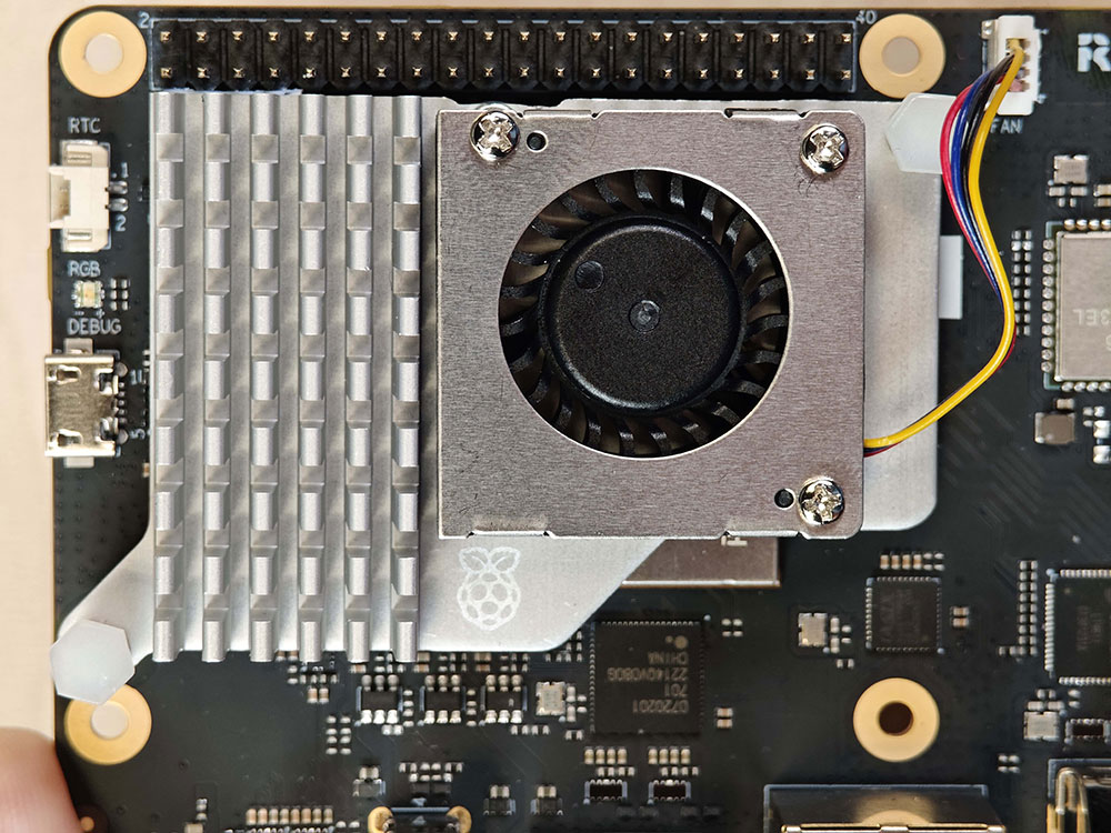
When using RUBIK Pi 3 in high-load or high-performance scenarios, use cooling measures to ensure that the performance of the device is stable. Otherwise, performance may fluctuate due to high CPU temperature.
2.8.1 Install the fan
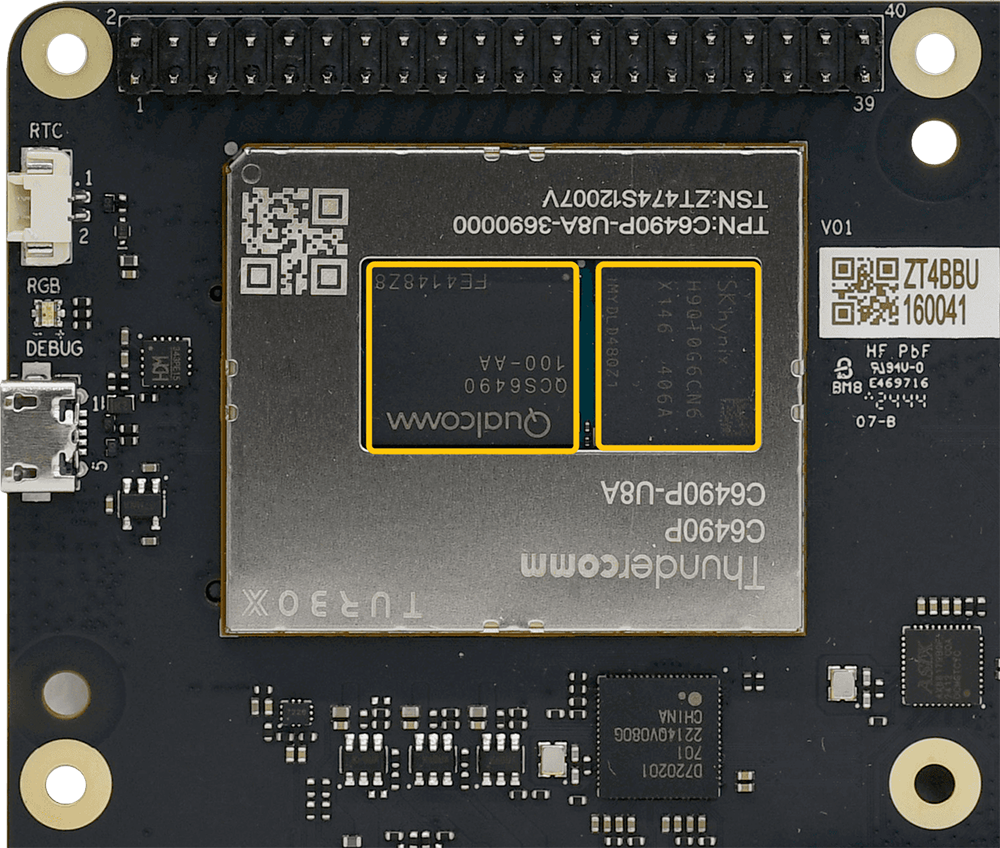
- Remove the thermal pads on the back of the cooler and cut the following two pads in the shape of SoC and uMCP of RUBIK Pi 3.
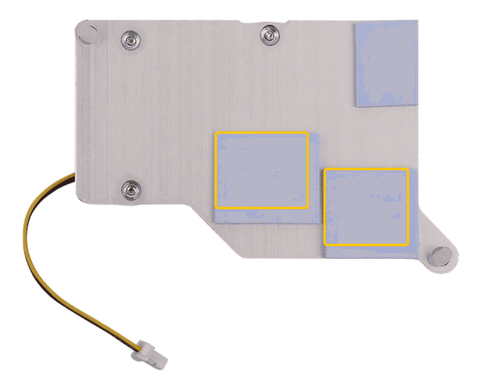
The dimensions of the two pieces are about 14 x 12mm and 13 x 11.5mm respectively.
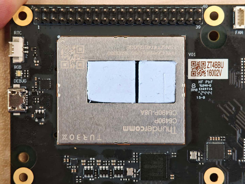
- Paste the two thermal pads to the corresponding positions on RUBIK Pi 3.
- Install the cooler.
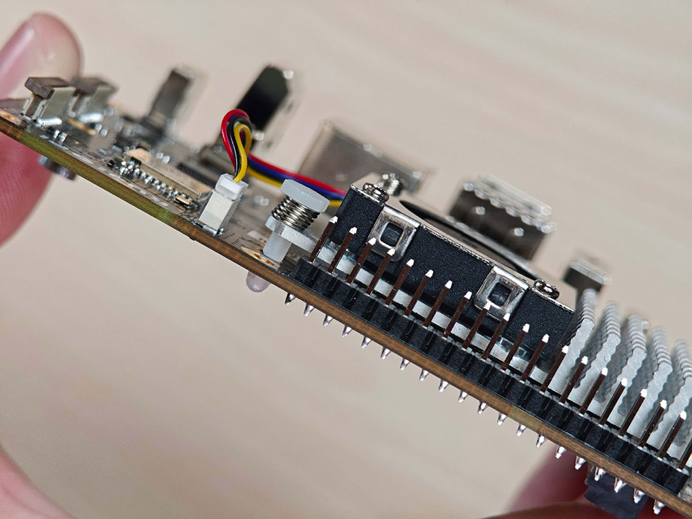
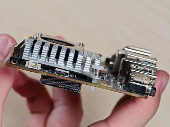
- Connect the fan cable.
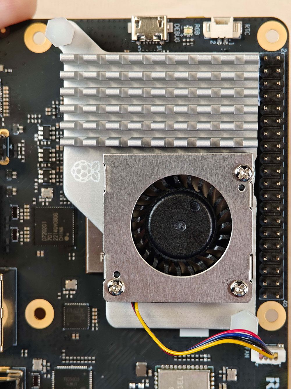
We recommend that you do not remove the fan after installing it on the RUBIK Pi 3. Removal will cause the fan's push pins and thermal pads to degrade and may result in product damage. If the push pins are damaged or deformed, or if they do not clip securely, stop using the fan.
2.8.2 Control the fan
The fan of RUBIK Pi 3 controls the speed according to the CPU temperature. You can also run the following commands on RUBIK Pi 3 to control the fan speed. 0 and 255 indicate the maximum and minimum speed of the fan respectively.
echo 100 > /sys/class/hwmon/hwmon29/pwm1
echo 255 > /sys/class/hwmon/hwmon29/pwm1
echo 0 > /sys/class/hwmon/hwmon29/pwm1
2.9 Ethernet
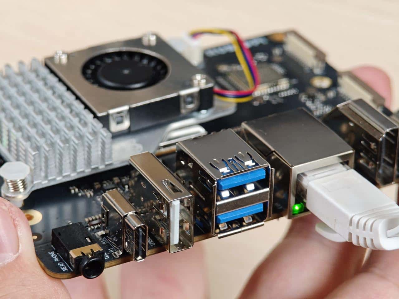
The Ethernet interface is port 8 in the following figure. RUBIK Pi 3 supports Gigabit Ethernet.
Connect the network cable, as shown in the following figure:
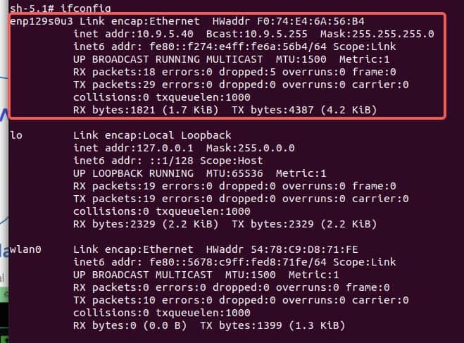
Run the following command to check the network connection on RUBIK Pi 3. As shown in the following figure, the IP has been successfully assigned, indicating that the network connection is successful:
2.10 RTC battery connector
The real-time clock (RTC) battery connector is port 1 in the following figure.

Connect the RTC battery as shown in the following figure and write the time into the system hardware clock of RUBIK Pi 3. This way, the system time of RUBIK Pi 3 can be saved even if it is completely powered off.
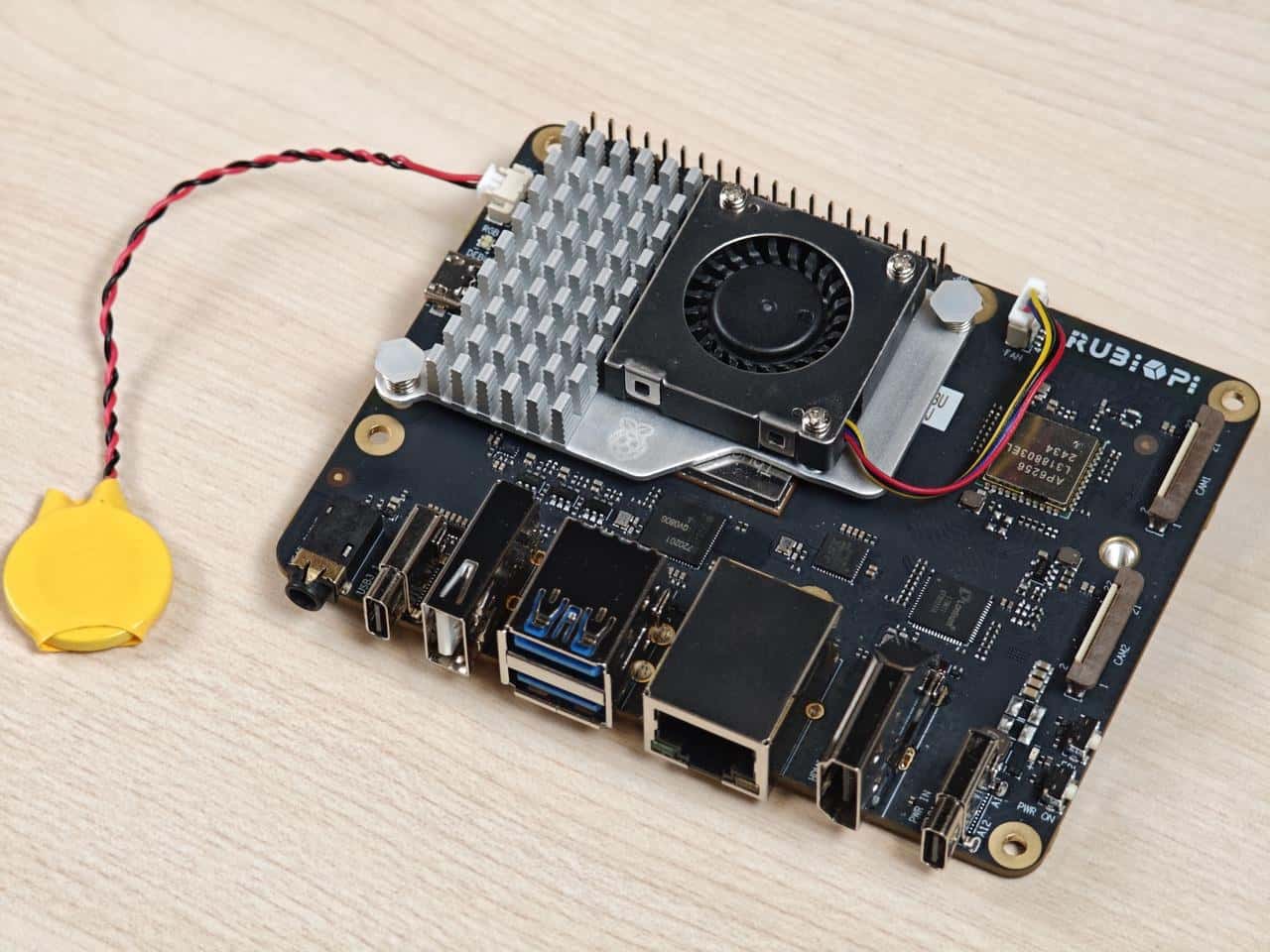
Write the system time to the system hardware clock on RUBIK Pi 3 as follows:
date -s "08:00:00 20241201" # Set system time to 08:00, December 1, 2024
hwclock -w # Write system time to system hardware clock
2.11 M.2 Key M connector
The M.2 Key M connector is connector 18 in the following figure:
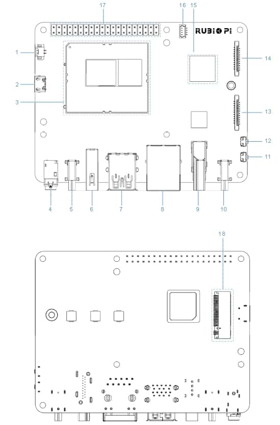
The M.2 Key M connector is compatible with the 2280-sized SSD, as shown in the following figures:
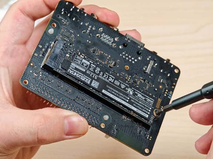
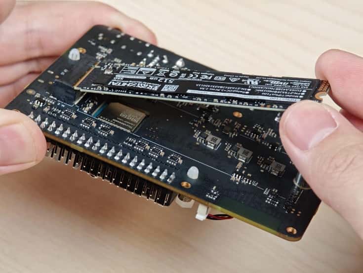
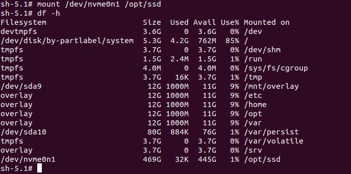
At present, RUBIK Pi 3 does not support automatic mounting of SSDs. Run the following commands on RUBIK Pi 3 to manually mount SSDs.
mkdir /opt/ssd
mount /dev/nvme0n1 /opt/ssd
