2. 外设与接口
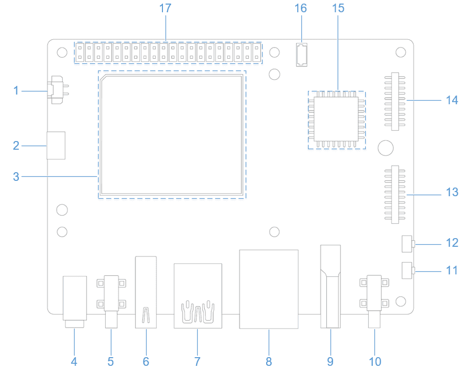
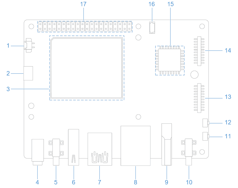
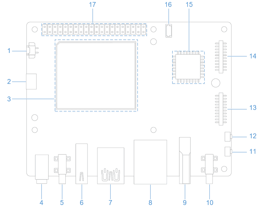
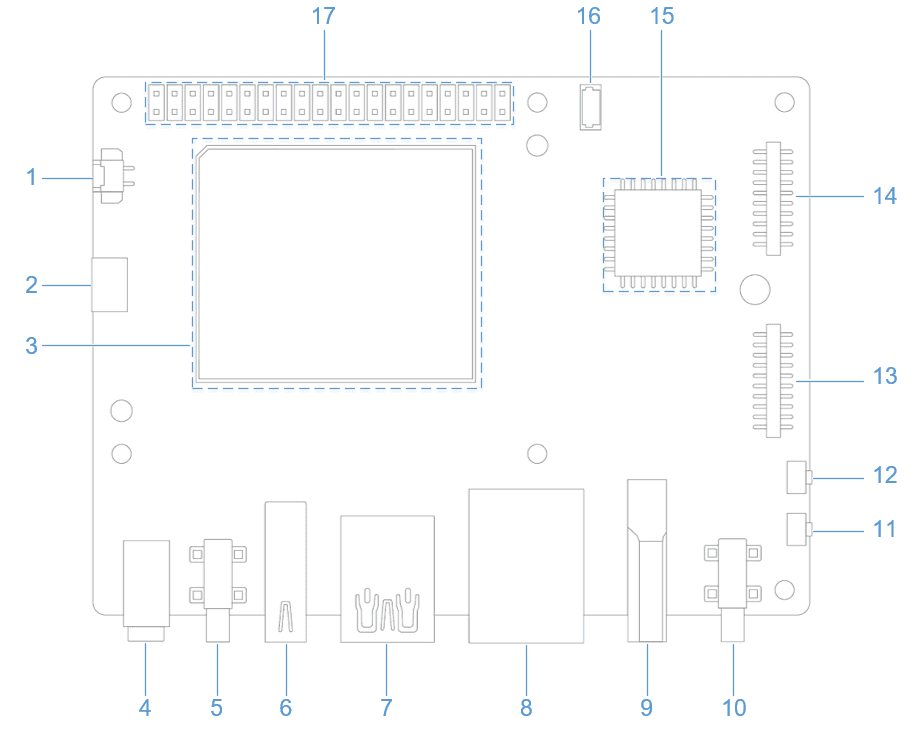
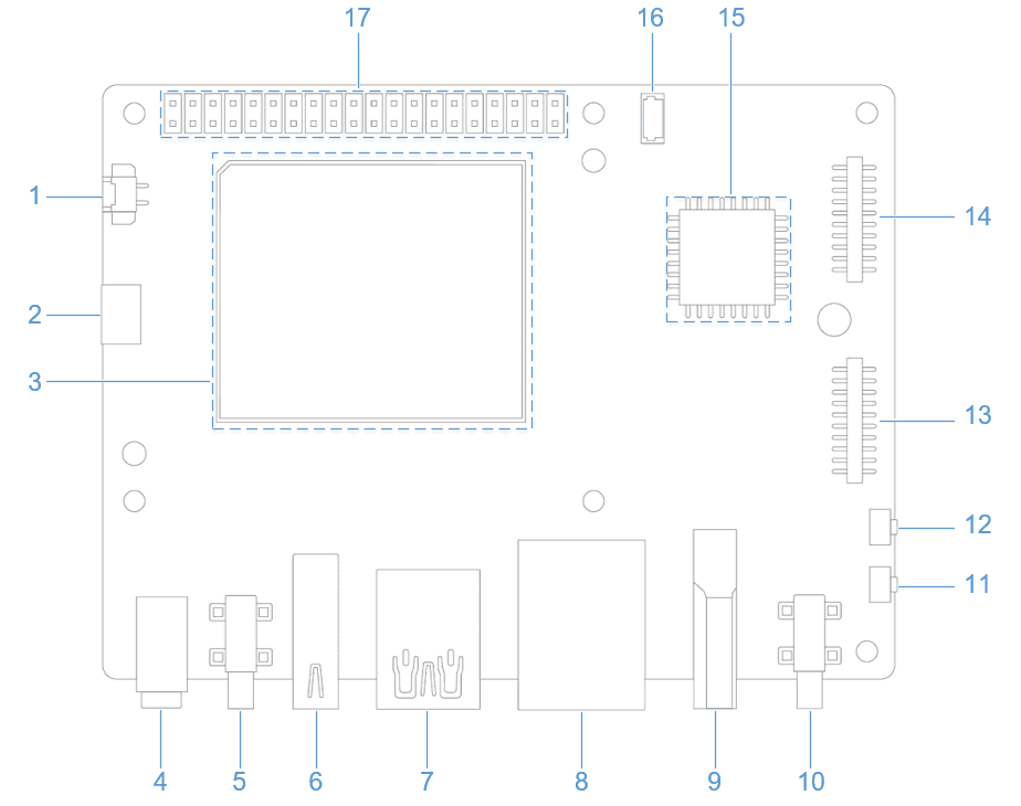
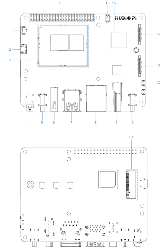
2.1 硬件资源图
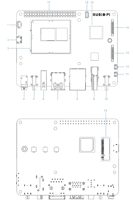
| 序号 | 接口 | 序号 | 接口 |
|---|---|---|---|
| 1 | RTC 电池接口 | 10 | Power Delivery over Type-C |
| 2 | Micro USB (UART 调试) | 11 | Power on 按键 |
| 3 | QCS6490 模组 | 12 | EDL 按键 |
| 4 | 3.5mm 耳机接口 | 13 | 摄像头接口 1 |
| 5 | USB Type-C with DP (USB3.1) | 14 | 摄像头接口 2 |
| 6 | USB Type-A (USB2.0) | 15 | Wi-Fi/BT 模块 |
| 7 | 2 x USB Type- A (USB3.0) | 16 | 风扇接口 |
| 8 | 1000M 以太网 | 17 | 40-pin 连接器 |
| 9 | HDMI OUT | 18 | M.2 Key M 接口 |
2.2 40 pin 连接器
2.2.1 GPIO
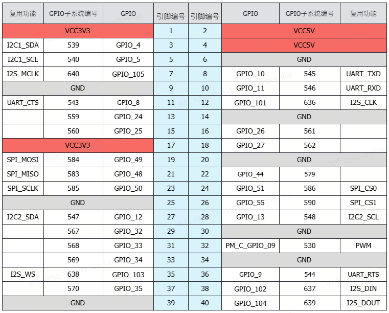
2.2.1.1 引脚分布
在用户空间使用 GPIO 时,通常需要使用 GPIO 的引脚编号,可以通过下表进行确认,下表中表明了 40 pin 连接器上的引脚功能,如13号引脚的引脚名称为 GPIO_24, GPIO 子系统的引脚编号为559。
2.2.1.2 使用shell命令控制
在 RUBIK Pi 3 中执行下面的步骤控制 GPIO
- 进入 /sys/class/gpio 目录:
cd /sys/class/gpio
- 将要控制的 GPI O导出,如控制13号引脚 GPIO_24:
echo 559 > export
- 进入到 gpio559 目录设置 GPIO 属性:
cd gpio559
ls

direction(方向):
- 输入:in
- 输出:out
value(值):
- 低电平:0
- 高电平:1
edge (中断边沿):
- 上升沿触发:rising
- 下降沿触发:falling
- 双边沿触发:both
- 禁用中断:none
如设置13号引脚输出高电平:
echo out > direction
echo 1 > value
- 取消导出13号引脚到用户空间:
echo 559 > unexport
2.2.1.3 使用Python程序控制
- 可使用 Python 的 periphery 库控制 GPIO,可在 RUBIK Pi 3 中使用下面命令进行安装:
pip3 install python-periphery
- 下方截取代码是使用 periphery 库操作 GPIO 的示例,其中将13号引脚设置为输出,15号引脚设置为输入,循环检测15号引脚的电平状态。
from periphery import GPIO
import time

out_gpio = GPIO(559, "out")
in_gpio = GPIO(560, "in")

try:
    while True:
        try:
            out_gpio.write(True)
            pin_level = in_gpio.read()
            print(f"in_gpio level: {pin_level}")

            out_gpio.write(False)
            pin_level = in_gpio.read()
            print(f"in_gpio level: {pin_level}")

            time.sleep(1)

        except KeyboardInterrupt:
            out_gpio.write(False)
            break

except IOError:
    print("Error")

finally:
    out_gpio.close()
    in_gpio.close()
- 将 gpio.py 传输到 RUBIK Pi 3 中,如使用 ADB 传输。
adb push gpio.py /opt
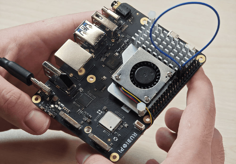
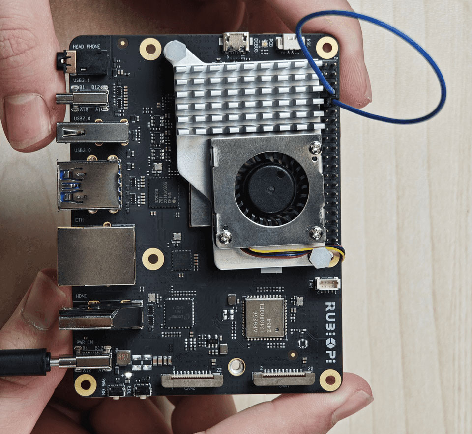
- 将13和15号引脚使用杜邦线短接测试 GPIO 电平控制和电平读取情况,如下图所示:
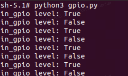
程序运行结果如下:
cd /opt
python3 gpio.py
2.2.1.4 使用C语言程序控制
- 以下代码示例,代码将13号引脚设置为输出15号引脚设置为输入,循环检测15号引脚的电平状态:
#include <stdio.h>
#include <stdlib.h>
#include <unistd.h>

int out_gpio = 559;
int in_gpio = 560;

int main() {
    char export_path[50] = {};
    char export_command[100] = {};
    snprintf(export_path, sizeof(export_path), "/sys/class/gpio/export");
    snprintf(export_command, sizeof(export_command), "echo %d > %s ", out_gpio, export_path);
    system(export_command);
    snprintf(export_command, sizeof(export_command), "echo %d > %s ", in_gpio, export_path);
    system(export_command);

    char direction_path[50] = {};
    snprintf(direction_path, sizeof(direction_path), "/sys/class/gpio/gpio%d/direction", out_gpio);
    FILE *direction_file = fopen(direction_path, "w");
    if (direction_file == NULL) {
        perror("Failed to open GPIO direction file");
        return -1;
    }
    fprintf(direction_file, "out");
    fclose(direction_file);

    snprintf(direction_path, sizeof(direction_path), "/sys/class/gpio/gpio%d/direction", in_gpio);
    direction_file = fopen(direction_path, "w");
    if (direction_file == NULL) {
        perror("Failed to open GPIO direction file");
        return -1;
    }
    fprintf(direction_file, "in");
    fclose(direction_file);

    char value_in_path[50] = {};
    char value_out_path[50] = {};
    char cat_command[100] = {};
    snprintf(value_out_path, sizeof(value_out_path), "/sys/class/gpio/gpio%d/value", out_gpio);
    snprintf(value_in_path, sizeof(value_in_path), "/sys/class/gpio/gpio%d/value", in_gpio);
    snprintf(cat_command, sizeof(cat_command), "cat %s", value_in_path);

    FILE *value_out_file = fopen(value_out_path, "w");
    if (value_out_file == NULL) {
        perror("Failed to open GPIO value file");
        return -1;
    }

    for (int i = 0; i < 5; i++) {
        fprintf(value_out_file, "1");
        fflush(value_out_file);

        system(cat_command);
        sleep(1);

        fprintf(value_out_file, "0");
        fflush(value_out_file);

        system(cat_command);
        sleep(1);
    }

    fclose(value_out_file);

    char unexport_path[50] = {};
    char unexport_command[100] = {};
    snprintf(unexport_path, sizeof(unexport_path), "/sys/class/gpio/unexport");
    snprintf(unexport_command, sizeof(unexport_command), "echo %d > %s ", out_gpio, unexport_path);
    system(unexport_command);
    snprintf(unexport_command, sizeof(unexport_command), "echo %d > %s ", in_gpio, unexport_path);
    system(unexport_command);

    return 0;
}
- 交叉编译程序,具体可参考 1.11.3 交叉编译工具使用方法章节:
aarch64-qcom-linux-gcc gpio.c -o gpio --sysroot=/home/zhy/qcom_sdk_meta/sysroots/armv8-2a-qcom-linux/
- 将 gpio 传输到 RUBIK Pi 3 中,如使用 ADB 传输:
adb push gpio /opt
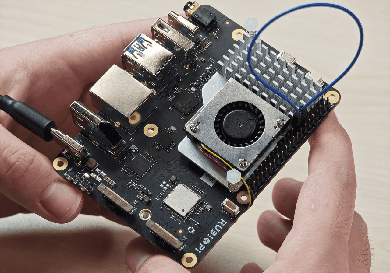
- 将13和15号引脚使用杜邦线短接,测试 GPIO 电平控制和电平读取情况,如下图所示,程序运行结果如下:
cd /opt
./gpio
2.2.2 I2C
2.2.2.1 引脚分布
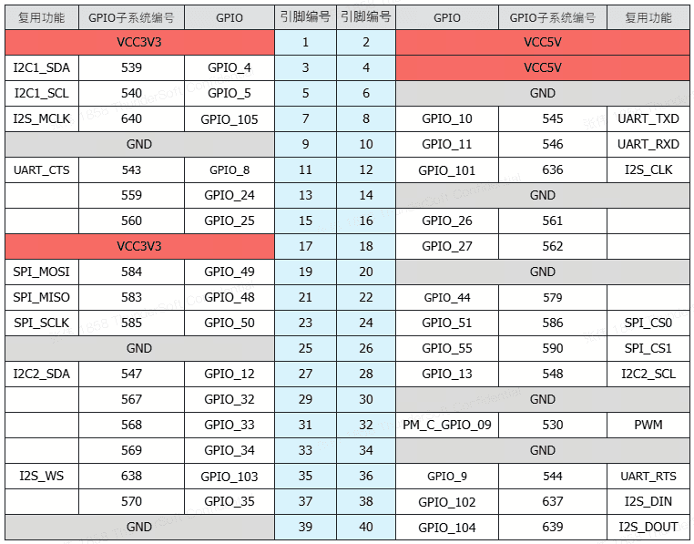
3号引脚和5号引脚默认已设置配为 I2C1。
2.2.2.2 使用 shell 命令测试
在 RUBIK Pi 3 中执行下面步骤控制 I2C 总线
- 查看I2C1接口上的设备:
i2cdetect -a -y -r 1
- 读取地址为0x38设备的全部寄存器:
i2cdump -f -y 3 0x38
- 向地址为0x38设备的0x01寄存器地址写入0xaa:
i2cset -f -y 1 0x38 0x01 0xaa
- 读取地址为0x38的设备,寄存器地址为0x01处的数值:
i2cget -f -y 1 0x38 0x01
2.2.2.3 使用 Python 程序 I2C 通信
- 可使用 Python 的 smbus 库控制 I2C,可在 RUBIK Pi 3 中使用下面命令进行安装:
pip3 install smbus
- 以下代码示例,使用 I2C1 总线和地址为0x38的设备进行通信,向设备0x01地址处写入0xaa:
import smbus

def main():
    data = [0x01, 0xaa]

    try:
        i2c_bus = smbus.SMBus(1)

        print("i2cdetect addr : ", end="")
        for address in range(0x7F):
            try:
                i2c_bus.write_i2c_block_data(address, 0, data)
                print("0x{:02X},".format(address), end="")
            except OSError:
                pass

        print()

    except Exception as e:
        print(f"An error occurred: {e}")

    finally:
        if i2c_bus:
            i2c_bus.close()

if __name__ == "__main__":
    main()
- 将i2c.py传输到 RUBIK Pi 3 中,如果使用 adb 传输,命令如下:
adb push i2c.py /opt
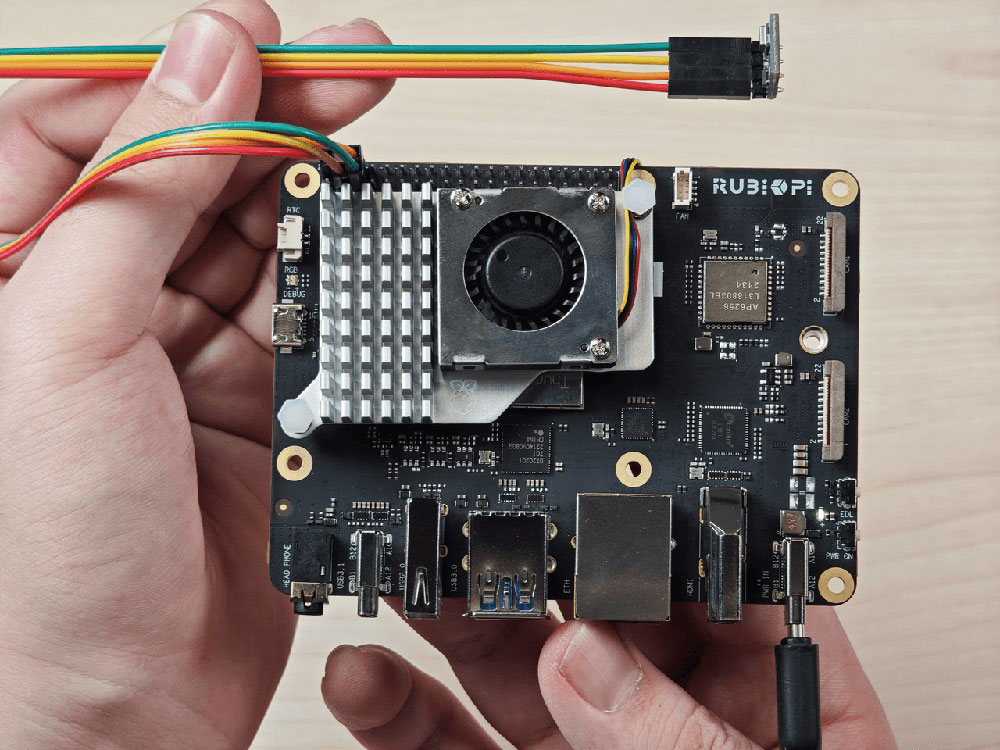
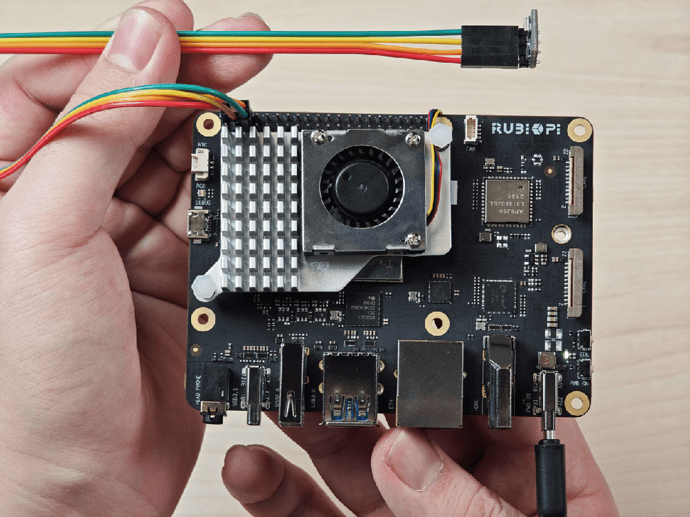
- 将3和5号引脚连接 I2C 传感器,验证 I2C 总线通信,如下图所示:
cd /opt
python3 i2c.py
程序运行结果如下:
2.2.2.4 使用C语言程序 I2C 通信
- 以下代码示例,I2C1 总线和地址为0x38的设备进行通信,向设备0x01地址处写入0xaa:
#include <stdio.h>
#include <stdlib.h>
#include <stdint.h>
#include <fcntl.h>
#include <unistd.h>
#include <linux/i2c-dev.h>
#include <sys/ioctl.h>

#define I2C_DEVICE_PATH "/dev/i2c-1"

int main() {
    uint8_t data[2] = {0x01,0xaa};

    const char *i2c_device = I2C_DEVICE_PATH;
    int i2c_file;

    if ((i2c_file = open(i2c_device, O_RDWR)) < 0) {
        perror("Failed to open I2C device");
        return -1;
    }

    ioctl(i2c_file, I2C_TENBIT, 0);
    ioctl(i2c_file, I2C_RETRIES, 5);

    printf("i2cdetect addr : ");
    for (int x = 0; x < 0x7f; x++)
    {
        if (ioctl(i2c_file, I2C_SLAVE, x) < 0) {
            perror("Failed to set I2C slave address");
            close(i2c_file);
            return -1;
        }

        if (write(i2c_file, data, 2) == 2)
        {
            printf("0x%x,", x);
        }
    }

    close(i2c_file);
    printf("\r\n");

    return 0;
}
- 交叉编译程序,具体可参考1.11.3交叉编译工具使用方法章节:
aarch64-qcom-linux-gcc i2c.c -o i2c --sysroot=/home/zhy/qcom_sdk_meta/sysroots/armv8-2a-qcom-linux/
- 将i2c传输到 RUBIK Pi 3 中,如果使用 ADB 传输,命令如下:
adb push i2c /opt
- 将3和5号引脚连接 I2C 传感器,验证 I2C 总线通信,如下图所示:
cd /opt
./i2c
程序运行结果如下:
2.2.3 SPI
2.2.3.1 引脚分布
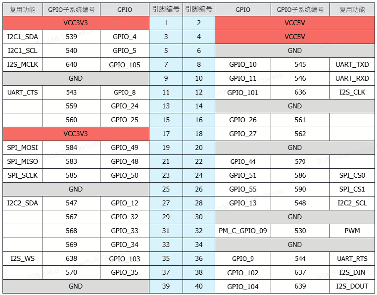
19号、21号、23号、24号 引脚默认已设置配为SPI。
2.2.3.2 使用 Python 程序 SPI 通信
- 可使用 Python 的 spidev 库进行SPI通信,spidev 库可在 RUBIK Pi 3 中使用下面命令进行安装:
pip3 install spidev
- 以下代码示例,代码使用 SPI 总线进行数据收发通信:
import spidev

def main():
    tx_buffer = [ord(char) for char in "hello world!"]
    rx_buffer = [0] * len(tx_buffer)

    try:
        spi = spidev.SpiDev()
        spi.open(12, 0)
        spi.max_speed_hz = 1000000

        rx_buffer = spi.xfer2(tx_buffer[:])
        print("tx_buffer:\n\r", ''.join(map(chr, tx_buffer)))
        print("rx_buffer:\n\r", ''.join(map(chr, rx_buffer)))

    except Exception as e:
        print(f"An error occurred: {e}")

    finally:
        if spi:
            spi.close()

if __name__ == "__main__":
    main()
- 将spi.py传输到 RUBIK Pi 3 中,如果使用 ADB 传输,命令如下:
adb push spi.py /opt
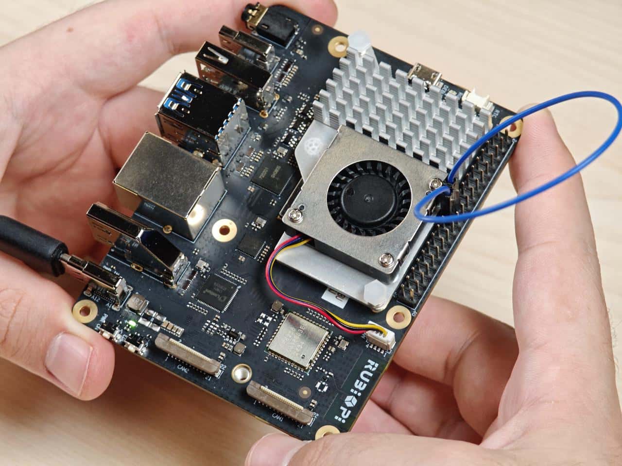
- 将19号引脚和21号引脚使用杜邦线短接,验证 SPI 总线通信,如下图所示:
python3 spi.py
程序运行结果如下:
2.2.3.3 使用C语言程序 SPI 通信
- 以下代码示例,代码使用 SPI 总线进行数据收发通信:
#include <stdio.h>
#include <stdlib.h>
#include <stdint.h>
#include <fcntl.h>
#include <unistd.h>
#include <linux/spi/spidev.h>
#include <sys/ioctl.h>

#define SPI_DEVICE_PATH "/dev/spidev12.0"

int main() {
    int spi_file;
    uint8_t tx_buffer[50] = "hello world!";
    uint8_t rx_buffer[50];

    // Open the SPI device
    if ((spi_file = open(SPI_DEVICE_PATH, O_RDWR)) < 0) {
        perror("Failed to open SPI device");
        return -1;
    }

    // Configure SPI mode and bits per word
    uint8_t mode = SPI_MODE_0;
    uint8_t bits = 8;
    if (ioctl(spi_file, SPI_IOC_WR_MODE, &mode) < 0) {
        perror("Failed to set SPI mode");
        close(spi_file);
        return -1;
    }
    if (ioctl(spi_file, SPI_IOC_WR_BITS_PER_WORD, &bits) < 0) {
        perror("Failed to set SPI bits per word");
        close(spi_file);
        return -1;
    }

    // Perform SPI transfer
    struct spi_ioc_transfer transfer = {
        .tx_buf = (unsigned long)tx_buffer,
        .rx_buf = (unsigned long)rx_buffer,
        .len = sizeof(tx_buffer),
        .delay_usecs = 0,
        .speed_hz = 1000000,  // SPI speed in Hz
        .bits_per_word = 8,
    };

    if (ioctl(spi_file, SPI_IOC_MESSAGE(1), &transfer) < 0) {
        perror("Failed to perform SPI transfer");
        close(spi_file);
        return -1;
    }

     /* Print tx_buffer and rx_buffer*/
    printf("\rtx_buffer: \n %s\n ", tx_buffer);
    printf("\rrx_buffer: \n %s\n ", rx_buffer);

    // Close the SPI device
    close(spi_file);

    return 0;
}
- 交叉编译程序,具体可参考1.11.3交叉编译工具使用方法章节:
aarch64-qcom-linux-gcc spi.c -o spi --sysroot=/home/zhy/qcom_sdk_meta/sysroots/armv8-2a-qcom-linux/
- 将spi传输到 RUBIK Pi 3 中,如果使用 ADB 传输,命令如下:
adb push spi /opt
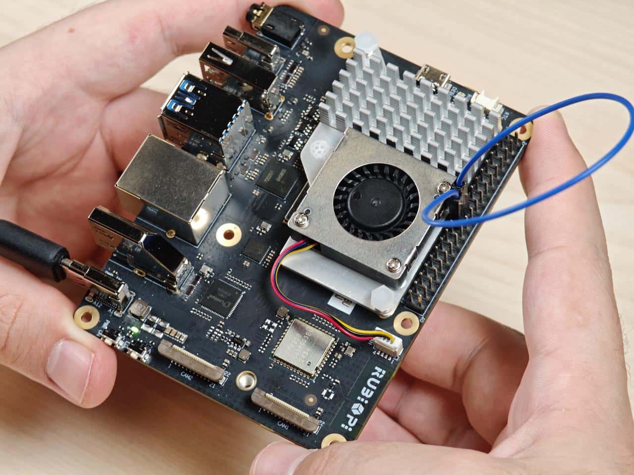
- 将19号引脚和21号引脚使用杜邦线短接,验证 SPI 总线通信,如下图所示:
cd /opt
./spi
程序执行结果如下:
2.2.4 UART
2.2.4.1 引脚分布
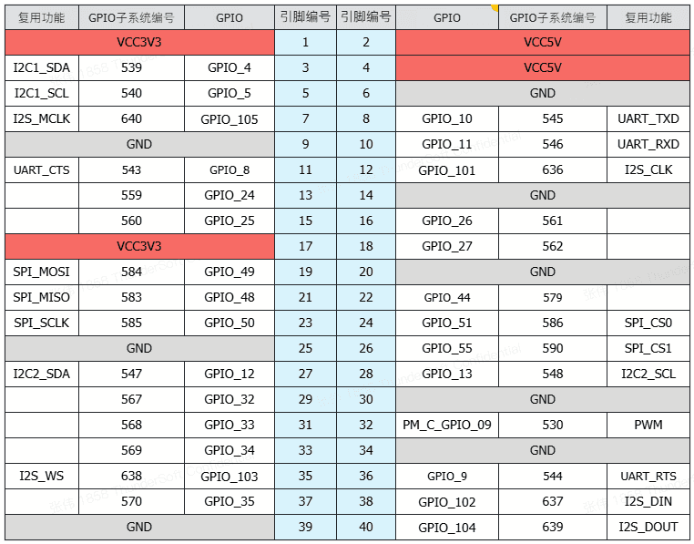
8号和10号引脚默认已设置配为 UART,设备节点为 /dev/ttyHS3。
2.2.4.2 使用shell命令测试
在 RUBIK Pi 3 中 使用下面命令控制串口通信
- 使用 stty 工具配置串口,如下将串口的输入速率和输出速率都设置为115200,并关闭回显:
stty -F /dev/ttyHS3 ispeed 115200 ospeed 115200
stty -F /dev/ttyHS3 -echo
- 在 RUBIK Pi 3 上开启两个终端,将8号引脚和10号引脚使用杜邦线短接,分别执行下面命令,接收端会回显发送端的内容:
echo "hello world!" > /dev/ttyHS3  #发送端
cat /dev/ttyHS3 #接收端
2.2.4.3 使用 Python 程序 UART 通信
- 可使用 Python 的 serial 库进行 UART 通信,可在 RUBIK Pi 3 中使用下面命令进行安装:
pip3 install pyserial
- 以下代码示例,使用UART进行数据收发通信:
import serial
import time

with serial.Serial(
    "/dev/ttyHS3",
    baudrate=115200,
    bytesize=serial.EIGHTBITS,
    stopbits=serial.STOPBITS_ONE,
    parity=serial.PARITY_NONE,
    timeout=1,
) as uart3:
    uart3.write(b"Hello World!\n")
    buf = uart3.read(128)
    print("Raw data:\n", buf)
    data_strings = buf.decode("utf-8")
    print("Read {:d} bytes, printed as string:\n {:s}".format(len(buf), data_strings))
- 将uart.py传输到 RUBIK Pi 3 中,如果使用 ADB 传输,命令如下:
adb push uart.py /opt
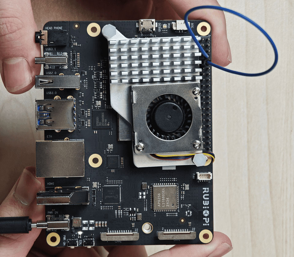
- 将8号引脚和10号引脚使用杜邦线短接,验证串口通信,如下图所示:
python3 uart.py
程序执行结果如下:
2.2.4.4 使用C语言程序 UART 通信
- 以下代码示例,使用 UART 进行数据收发通信:
#include <stdio.h>
#include <stdlib.h>
#include <string.h>
#include <fcntl.h>
#include <termios.h>
#include <unistd.h>

int main() {
    int serial_port_num = 3;
    char serial_port[15];

    sprintf(serial_port,"/dev/ttyHS%d",serial_port_num);
    int serial_fd;

    serial_fd = open(serial_port, O_RDWR | O_NOCTTY);
    if (serial_fd == -1) {
        perror("Failed to open serial port");
        return 1;
    }

    struct termios tty;
    memset(&tty, 0, sizeof(tty));

    if (tcgetattr(serial_fd, &tty) != 0) {
        perror("Error from tcgetattr");
        return 1;
    }

    cfsetospeed(&tty, B9600);
    cfsetispeed(&tty, B9600);

    tty.c_cflag &= ~PARENB;
    tty.c_cflag &= ~CSTOPB;
    tty.c_cflag &= ~CSIZE;
    tty.c_cflag |= CS8;

    if (tcsetattr(serial_fd, TCSANOW, &tty) != 0) {
        perror("Error from tcsetattr");
        return 1;
    }

    char tx_buffer[] = "hello world!\n";
    ssize_t bytes_written = write(serial_fd, tx_buffer, sizeof(tx_buffer));
    if (bytes_written < 0) {
        perror("Error writing to serial port");
        close(serial_fd);
        return 1;
    }
    printf("\rtx_buffer: \n %s ", tx_buffer);

    char rx_buffer[256];
    int bytes_read = read(serial_fd, rx_buffer, sizeof(rx_buffer));
    if (bytes_read > 0) {
        rx_buffer[bytes_read] = '\0';
        printf("\rrx_buffer: \n %s ", rx_buffer);
    } else {
        printf("No data received.\n");
    }

    close(serial_fd);

    return 0;
}
- 交叉编译程序,具体可参考1.11.3交叉编译工具使用方法章节:
aarch64-qcom-linux-gcc uart.c -o uart --sysroot=/home/zhy/qcom_sdk_meta/sysroots/armv8-2a-qcom-linux/
- 将uart传输到 RUBIK Pi 3 中,如果使用 ADB 传输,命令如下:
adb push uart /opt
- 将8号引脚和10号引脚使用杜邦线短接,验证串口通信,如下图所示:

2.3 USB
RUBIK Pi 3 拥有4个 USB 口:
- 两个 USB3.0 口,只能作为主机模式使用,如下图7。
- 一个 USB2.0 口,可以作为主机或设备模式使用,如下图6。
- 一个 USB3.1 Gen 1 口,可以作为主机或设备模式,以及 DP 显示使用,如下图5。
2.3.1 USB2.0 接口
USB2.0接口作为 device 模式时需要手动执行命令切换,如下为一种测试方式,在 RUBIK Pi 3 中输入下面命令,将 RUBIK Pi 3 模拟为U盘:
cd /sys/kernel/config/usb_gadget/  #在串口终端登录,执行下面命令
mkdir g1
cd g1
mkdir functions/mass_storage.0

dd if=/dev/zero of=/tmp/test.iso bs=1M count=2048  #创建大小为2G的U盘空间
mkfs.ext4 /tmp/test.iso
echo "/tmp/test.iso" > functions/mass_storage.0/lun.0/file
mkdir configs/c.1
ln -s functions/mass_storage.0/ configs/c.1/f3
mount -t debugfs none /sys/kernel/debug/

echo device > /sys/kernel/debug/usb/8c00000.usb/qcom_usb2_0_mode  #将USB切换为device模式
echo 8c00000.usb > UDC #连接USB线,U盘被识别 可在U盘内写入和写出文件

echo host > /sys/kernel/debug/usb/8c00000.usb/qcom_usb2_0_mode  #拔掉USB线,切换为主机模式
2.3.2 Type-C 接口
Type-C 接口可自动完成主机和设备模式的切换。
-
当 Type-C 接入 PC 时自动切换为设备模式。
-
接入 OTG 线时自动切换为主机模式。
-
接入 DP 显示器时,自动输出 DP 视频信号。
2.4 CSI
目前 RUBIK Pi 3 已经支持树莓派官方的三款摄像头:
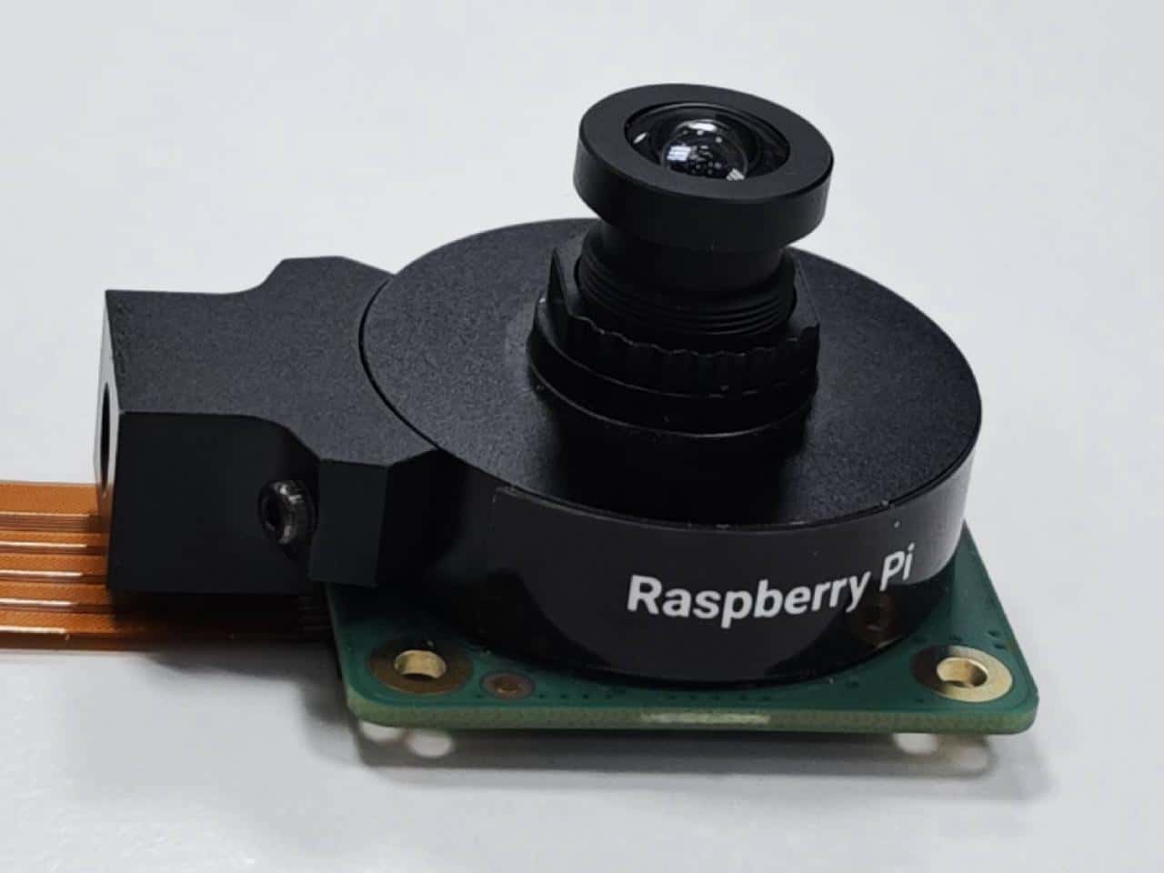
- Raspberry Pi High Quality Camera(IMX477/M12 Mount)
https://www.raspberrypi.com/products/raspberry-pi-high-quality-camera/
在 RUBIK Pi 3 QIM 官方演示中,IMX477 摄像头使用了 WS1053516 镜头.
- Raspberry Pi Camera Module 2 (IMX219)
https://www.raspberrypi.com/products/camera-module-v2/
目前 RUBIK Pi 3 暂时只支持标准版 Module 2 摄像头,不支持广角(Wide)、夜光(NoIR)版本。
- Raspberry Pi Camera Module 3 (IMX708)
https://www.raspberrypi.com/products/camera-module-3/
目前 RUBIK Pi 3 暂时只支持标准版 Module 3 摄像头,不支持广角(Wide)、夜光(NoIR)版本。当前软件版本暂不支持 Module 3 摄像头的AF自动对焦功能。
2.4.1 摄像头排线安装
https://www.raspberrypi.com/products/camera-cable/
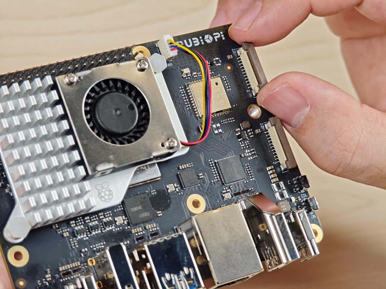
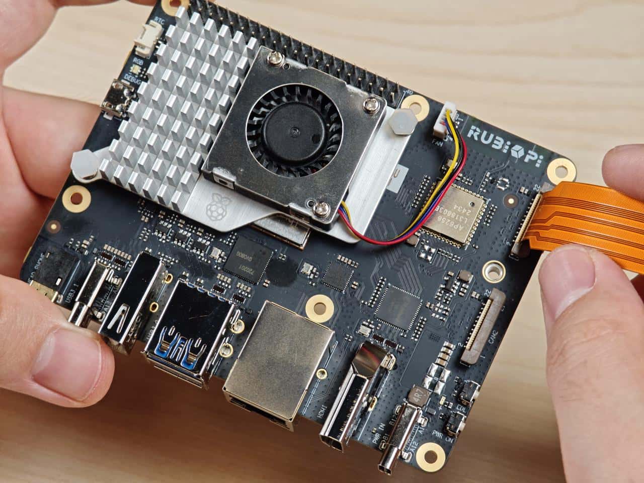
RUBIK Pi 3 支持的摄像头 FPC 为 22Pin,0.5mm 间距,厚度0.3±0.05mm。可以兼容树莓派5同规格摄像头 FPC。

1.向上拉开连接器的锁扣部分:
2.插入 FPC,注意接触面朝向板内:

3.按下锁扣,确认 FPC 稳定没有松动:
2.4.2 摄像头使用方法
在 RUBIK Pi 3 中,可使用 gstreamer 命令对摄像头进行操作,操作前需输入下面命令对摄像头进行设置:
mount -o remount,rw /
echo multiCameraLogicalXMLFile=kodiak_dc.xml > /var/cache/camera/camxoverridesettings.txt
echo enableNCSService=FALSE >> /var/cache/camera/camxoverridesettings.txt
可将摄像头插入,下图13和14处:
如下为实物连接图:

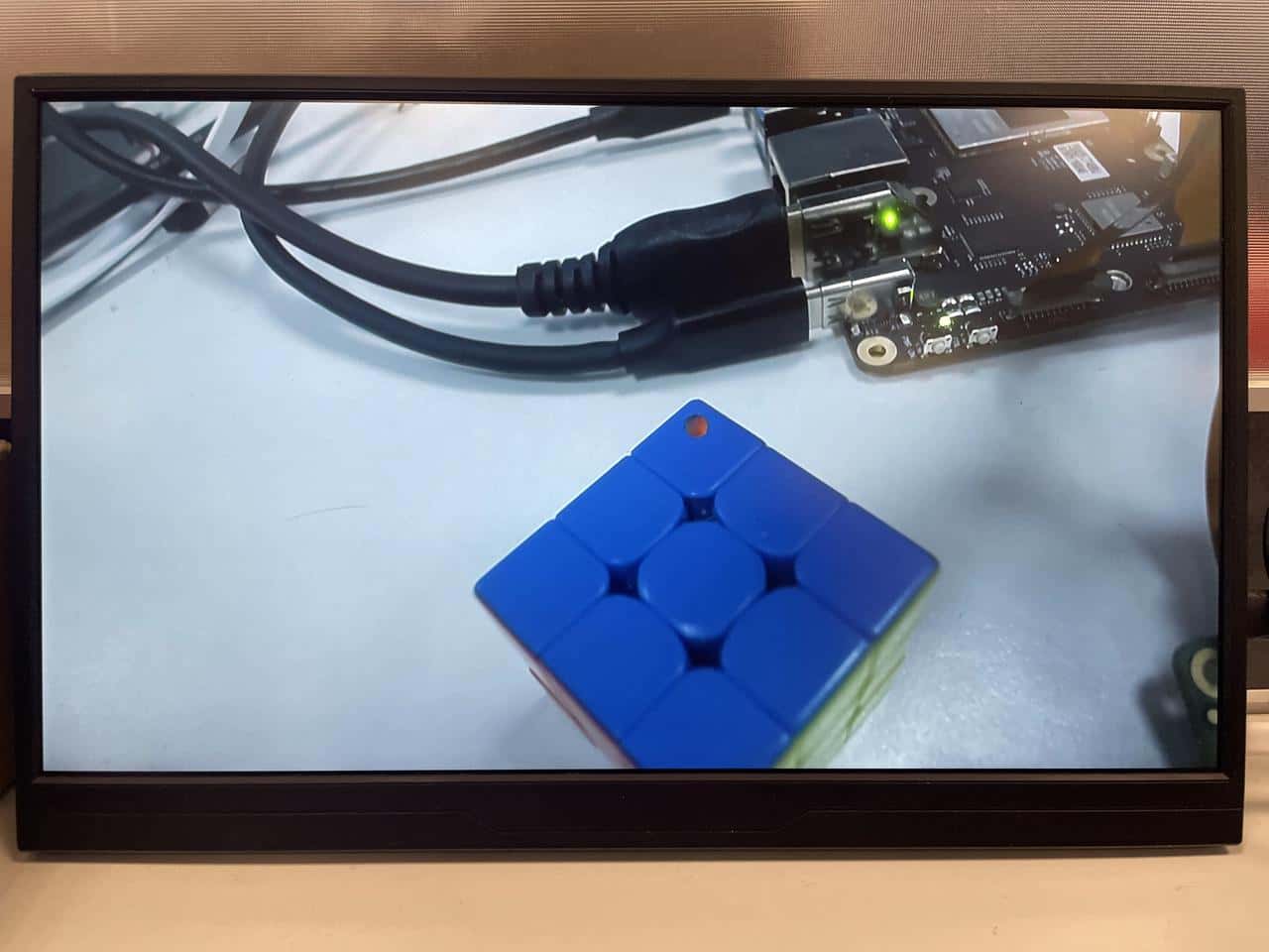
- 在 RUBIK Pi 3 中使用下面命令测试单个摄像头全屏预览:
export XDG_RUNTIME_DIR=/dev/socket/weston
export WAYLAND_DISPLAY=wayland-1
setprop persist.overlay.use_c2d_blit 2
gst-launch-1.0 -e qtiqmmfsrc camera=0 name=camsrc ! video/x-raw\(memory:GBM\),format=NV12,width=1920,height=1080,framerate=30/1,compression=ubwc ! queue ! waylandsink fullscreen=true async=true
- 在 RUBIK Pi 3 中使用下面命令测试两摄像头并发预览:
#终端1
export XDG_RUNTIME_DIR=/dev/socket/weston
export WAYLAND_DISPLAY=wayland-1
setprop persist.overlay.use_c2d_blit 2
gst-launch-1.0 -e qtiqmmfsrc camera=0 name=camsrc ! video/x-raw\(memory:GBM\),format=NV12,width=1920,height=1080,framerate=30/1,compression=ubwc ! queue ! waylandsink sync=false x=0 y=0 width=960 height=540 enable-last-sample=false

#终端2
export XDG_RUNTIME_DIR=/dev/socket/weston
export WAYLAND_DISPLAY=wayland-1
setprop persist.overlay.use_c2d_blit 2
gst-launch-1.0 -e qtiqmmfsrc camera=1 name=camsrc ! video/x-raw\(memory:GBM\),format=NV12,width=1920,height=1080,framerate=30/1,compression=ubwc ! queue ! waylandsink sync=false x=960 y=540 width=960 height=540 enable-last-sample=false

- 在 RUBIK Pi 3 中使用下面命令测试两摄像头并发录像:
#终端1:
echo multiCameraLogicalXMLFile=kodiak_dc.xml > /var/cache/camera/camxoverridesettings.txt
export XDG_RUNTIME_DIR=/dev/socket/weston
export WAYLAND_DISPLAY=wayland-1
setprop persist.overlay.use_c2d_blit 2
gst-launch-1.0 -e qtiqmmfsrc camera=0 name=camsrc video_0::type=preview ! video/x-raw\(memory:GBM\),format=NV12,width=1920,height=1080,framerate=30/1,compression=ubwc,interlace-mode=progressive,colorimetry=bt601 ! queue ! v4l2h264enc capture-io-mode=5 output-io-mode=5 ! queue ! h264parse ! mp4mux ! queue ! filesink location="/opt/mux0.mp4"

#终端2:
export XDG_RUNTIME_DIR=/dev/socket/weston
export WAYLAND_DISPLAY=wayland-1
setprop persist.overlay.use_c2d_blit 2
gst-launch-1.0 -e qtiqmmfsrc camera=1 name=camsrc video_0::type=preview ! video/x-raw\(memory:GBM\),format=NV12,width=1920,height=1080,framerate=30/1,compression=ubwc,interlace-mode=progressive,colorimetry=bt601 ! queue ! v4l2h264enc capture-io-mode=5 output-io-mode=5 ! queue ! h264parse ! mp4mux ! queue ! filesink location="/opt/mux1.mp4"
录制完成后在 /opt 目录下有录制的视频文件,如下图:
- 在 RUBIK Pi 3 中使用下面命令测试两摄像头并发录像加预览
#终端1
export XDG_RUNTIME_DIR=/dev/socket/weston
export WAYLAND_DISPLAY=wayland-1
setprop persist.overlay.use_c2d_blit 2
gst-launch-1.0 -e qtiqmmfsrc camera=0 name=camsrc video_0::type=preview ! video/x-raw\(memory:GBM\),format=NV12,width=1920,height=1080,framerate=30/1,compression=ubwc,interlace-mode=progressive,colorimetry=bt601 ! queue ! v4l2h264enc capture-io-mode=5 output-io-mode=5 ! queue ! h264parse ! mp4mux ! queue ! filesink location="/opt/mux0.mp4" camsrc. ! video/x-raw\(memory:GBM\),format=NV12,width=1920,height=1080,framerate=30/1,compression=ubwc ! waylandsink sync=false x=0 y=0 width=960 height=540 enable-last-sample=false

#终端2
export XDG_RUNTIME_DIR=/dev/socket/weston
export WAYLAND_DISPLAY=wayland-1
setprop persist.overlay.use_c2d_blit 2
gst-launch-1.0 -e qtiqmmfsrc camera=1 name=camsrc video_0::type=preview ! video/x-raw\(memory:GBM\),format=NV12,width=1920,height=1080,framerate=30/1,compression=ubwc,interlace-mode=progressive,colorimetry=bt601 ! queue ! v4l2h264enc capture-io-mode=5 output-io-mode=5 ! queue ! h264parse ! mp4mux ! queue ! filesink location="/opt/mux1.mp4" camsrc. ! video/x-raw\(memory:GBM\),format=NV12,width=1920,height=1080,framerate=30/1,compression=ubwc ! waylandsink sync=false x=960 y=540 width=960 height=540 enable-last-sample=false
录制完成后在 /opt 目录下有录制的视频文件:
预览结果如下:

2.5 HDMI OUT
HDMI 接口为下图9, RUBIK Pi 3 支持 HDMI1.4,最高 4K 30Hz 输出,支持 CEC 功能,支持分辨率自适应功能(按屏幕支持的最高分辨率输出)和热插拔:
2.5.1 CEC
HDMI CEC(Consumer Electronics Control,消费者电子控制)是 HDMI 标准中的一项功能,旨在通过单一的HDMI连接线实现多设备之间的互联与统一控制。具体来说,CEC 允许连接的设备通过专用的 CEC 引脚进行通信,从而实现例如通过一个遥控器控制多台设备的功能。
RUBIK Pi 3 集成了 cec-client 工具,将 HDMI 线连接到电视后,可使用下面命令查看电视是否支持 CEC:
echo 'scan' | cec-client -s -d 1
若支持CEC将会有如下输出:
opening a connection to the CEC adapter...
requesting CEC bus information ...
CEC bus information
===================
device #0: TV
address:       0.0.0.0
active source: no
vendor:        Sony
osd string:    TV
CEC version:   1.4
power status:  standby
language:      eng


device #1: Recorder 1
address:       1.0.0.0
active source: no
vendor:        Pulse Eight
osd string:    CECTester
CEC version:   1.4
power status:  on
language:      eng


device #4: Playback 1
address:       3.0.0.0
active source: no
vendor:        Sony
osd string:    PlayStation 4
CEC version:   1.3a
power status:  standby
language:      ???
若电视支持CEC功能,可在 RUBIK Pi 3 中使用下面命令控制电视音量的加减:
echo 'volup' | cec-client -t p -s
echo 'voldown' | cec-client -t p -s
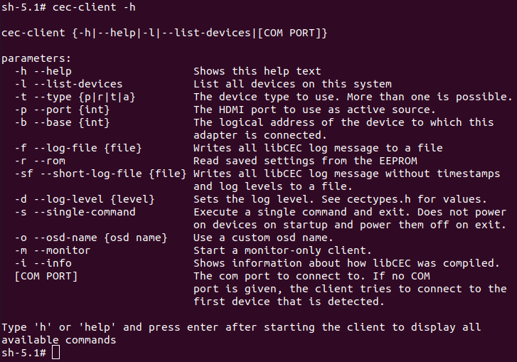
更多 cec-client 使用方法,可使用 -h 参数进行查看:
2.5.2 HDMI OUT 触摸屏
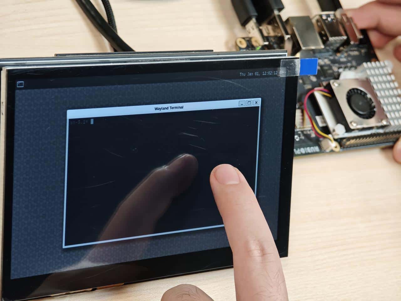
RUBIK Pi 3 默认支持1024*600P分辨率的HDMI OUT触摸屏,并支持触摸功能,如下图所示:
2.6 Wi-Fi & BT
RUBIK Pi 3 上搭载了 AP6256 Wi-Fi 模块,支持 Wi-Fi 5 和蓝牙5.2。
2.6.1 Wi-Fi
2.6.1.1 STA模式
在STA模式(Station)下,设备可连接到一个已经存在的无线网络,以便访问网络资源或互联网,在 RUBIK Pi 3 中输入如下面命令进行连接:
1.扫描附近Wi-Fi:
iw wlan0 scan | grep SSID
2.连接 Wi-Fi:
wpa_passphrase <ssid> <passphrase> > /etc/wpa_supplicant.conf  #输入Wi-Fi账号和密码

systemctl restart wifi  #连接Wi-Fi
3.连接好 Wi-Fi 后,下次开机会自动进行连接。
4.如想切换 Wi-Fi 可修改*/etc/wpa_supplicant.conf*文件,如下是一种修改方式:
ctrl_interface=/var/run/wpa_supplicant
update_config=1
pmf=1
network={
        ssid="RUBIKPi"
        psk="123456789"
}
-
ssid为无线网络名称
-
psk为无线网络密码
-
按实际情况对文件进行修改
修改完成后,输入下面命令进行连接:
killall -9 wpa_supplicant
wpa_supplicant -Dnl80211 -iwlan0 -c/etc/wpa_supplicant.conf -B
2.6.1.2 AP模式
AP模式(Access Point)即无线接入热点模式,是一个无线网络的创建者,是网络的中心节点,一般家庭或办公室使用的无线网络路由器就是一个AP,下面是AP的创建步骤:
-
开启AP
- 创建或修改*/opt/hostapd.conf* 文件:
ctrl_interface=/var/run/hostapd
driver=nl80211
ieee80211n=1
interface=wlan1
hw_mode=a
channel=36
beacon_int=100
dtim_period=1
ssid=RUBIKPi
auth_algs=1
ap_isolate=0
ignore_broadcast_ssid=0
wpa=2
wpa_key_mgmt=WPA-PSK
rsn_pairwise=CCMP
wpa_passphrase=123456789- 执行下面命令开启AP:
killall wpa_supplicant
killall dhcpcd
ifconfig wlan1 down
ifconfig wlan1 192.168.43.1 netmask 255.255.255.0 up
pkill -9 dnsmasq
dnsmasq -i wlan1 --dhcp-range=192.168.43.10,192.168.43.100
hostapd /opt/hostapd.conf & -
关闭AP:
hostapd_cli disable
killall -9 hostapd
ifconfig wlan1 down
2.6.2 BT
在RUBIK Pi 3中使用下面命令测试BT功能
-
运行 app_manager 程序进行配对:
cd /usr/src/rubikpi-bt-demo/
./app_manager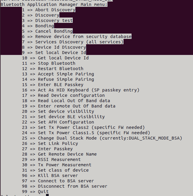
a.在终端输入2回车后等待蓝牙扫描结果;
b.在终端输入4回车后输入要配对的蓝牙设备 Dev 编号再次回车;
c.根据提示在终端输入13回车接受配对, 对端蓝牙设备同时也要接受配对请求;
d.app_manager 需要一直运行,下面步骤使用
adb shell命令创建新终端进行。 -
蓝牙发送
以发送文件为例:
cd /usr/src/rubikpi-bt-demo/
touch ./test_file.txt
echo RUBIKPi > test_file.txt
./app_opc
#输入4回车
#输入0回车
#输入设备编号回车
#手机接收文件
#输入9回车退出
- 蓝牙接收:
cd /usr/src/rubikpi-bt-demo/
mkdir push
./app_ops
#输入1回车
#手机蓝牙发送文件
#传输完成后,输入9回车退出, 在./push 文件夹中查看传输的文件
- 其他Demo
在 RUBIK Pi 3的 /usr/src/rubikpi-bt-demo/3rdparty/3rdparty/embedded/bsa_examples/linux 目录下,存放了所有 BT 相关的源码,可以按需要进行编译和查看,编译方法如下:
cd /usr/src/rubikpi-bt-demo/3rdparty/3rdparty/embedded/bsa_examples/linux/<测试demo>/build/
export ARMGCC=gcc
make CPU=arm64
cp arm64/<demo可执行文件>  /usr/src/rubikpi-bt-demo/
cd /usr/src/rubikpi-bt-demo/
#运行demo程序
2.7 音频
RUBIK Pi 3 目前支持的音接口为:
-
3.5mm 耳机,下图4。
-
HDMI OUT, 下图9。
-
蓝牙
2.7.1 查看声卡信息
- 在 RUBIK Pi 3 中输入下面命令,查看声卡挂载情况:
cat /proc/asound/cards
- 在 RUBIK Pi 3 中输入下面命令,查看已分配的 pcm 流列表:
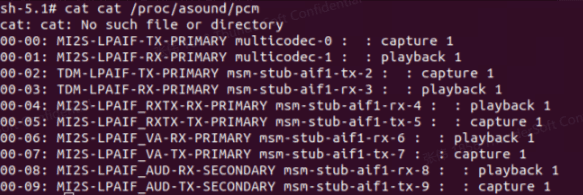
cat /proc/asound/pcm
2.7.2 设置输出源
在 RUBIK Pi 3 中输入下面命令,改变 gstreamer、paplay等命令的音频输出源头:
- 设置输出接口为3.5mm耳机接口
pactl set-sink-port 0 headset
- 设置输出接口为 HDMI
pactl set-sink-port 0 hdmi
2.7.3 播放
- 在 RUBIK Pi 3 中输入下面命令测试耳机播放, 将测试音频放到*/opt*目录下,执行下面命令进行播放:
gst-launch-1.0 filesrc location=/opt/test.mp3 ! mpegaudioparse ! mpg123audiodec ! pulsesink
- 在 RUBIK Pi 3 中输入下面命令测试 HDMI OUT 播放,将测试音频放到*/opt*目录下,执行下面命令进行播放:
systemctl stop pulseaudio
agmplay /opt/test.wav -D 100 -d 100 -r 48000 -b 16 -c 2 -i MI2S-LPAIF_RXTX-RX-PRIMARY
systemctl start pulseaudio
-
在 RUBIK Pi 3 中输入下面命令测试蓝牙耳机播放,测试需要开启多个终端。
- 终端一:
cd /usr/src/rubikpi-bt-demo/
./app_manager- 终端二:
cd /usr/src/rubikpi-bt-demo/
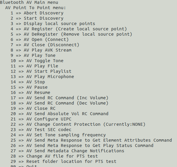
./app_av
a.输入2回车,等待发现蓝牙耳机;
b.输入6回车,开始建立连接;
c.输入1回车,从最近的扫描结果中连接;
d.输入要连接蓝牙设备的Dev号。
-
返回终端一,输入13回车,接受配对。
-
返回终端二,输入11回车后选择要播放的音乐编号回车播放音乐。
2.7.4 录制
在RUBIK Pi 3中输入下面命令测试录音功能
- 耳机录制:
gst-launch-1.0 -v pulsesrc volume=10 ! audioconvert ! wavenc ! filesink location=/opt/test.wav
-
蓝牙耳机录制,测试需要开启多个终端:
- 终端一:
cd /usr/src/rubikpi-bt-demo/
./app_manager- 终端二:
cd /usr/src/rubikpi-bt-demo/
./app_ag
a.输入 1 回车,等待发现蓝牙耳机;
b.输入 6 回车,连接蓝牙耳机;
c.输入 1 回车,从最近的扫描结果中连接;
d.输入要连接蓝牙设备的Dev号;
e.返回终端一,输入13回车,接受配对;
f.返回终端二,输入8 回车,打开 SCO 链路;
g.输入10回车,开始录制蓝牙耳机麦克风音频;
h.输入11回车停止录制;
i.录制音频的保存路径为 /usr/src/rubikpi-bt-demo/test_files/ag/sco_ag_in.wav。
2.7.5 调节音量
- 耳机调节音量
可通过下面命令获取和设置音量:
tinymix get "DAC Playback Volume"
tinymix set "DAC Playback Volume" 192 192
- 蓝牙调节音量
在播放蓝牙音频时,可在终端二输入 20 选择要连接编号回车后进行音量的调节,调节范围为0-100:
2.8 风扇
RUBIK Pi 3支持树莓派5的散热套件:
https://www.raspberrypi.com/products/active-cooler/
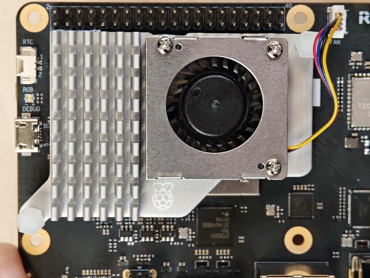
使用RUBIK Pi 3在运行一些高负载或高性能的场景下,需要使用散热措施来保证设备性能稳定,否则会因为cpu温度过高而带来降频等性能影响。
2.8.1 风扇安装
1.将散热器背面所有导热硅脂移除,将下图标记的两块硅脂按 RUBIK Pi 3 的 SoC 及 uMCP 的形状裁下。
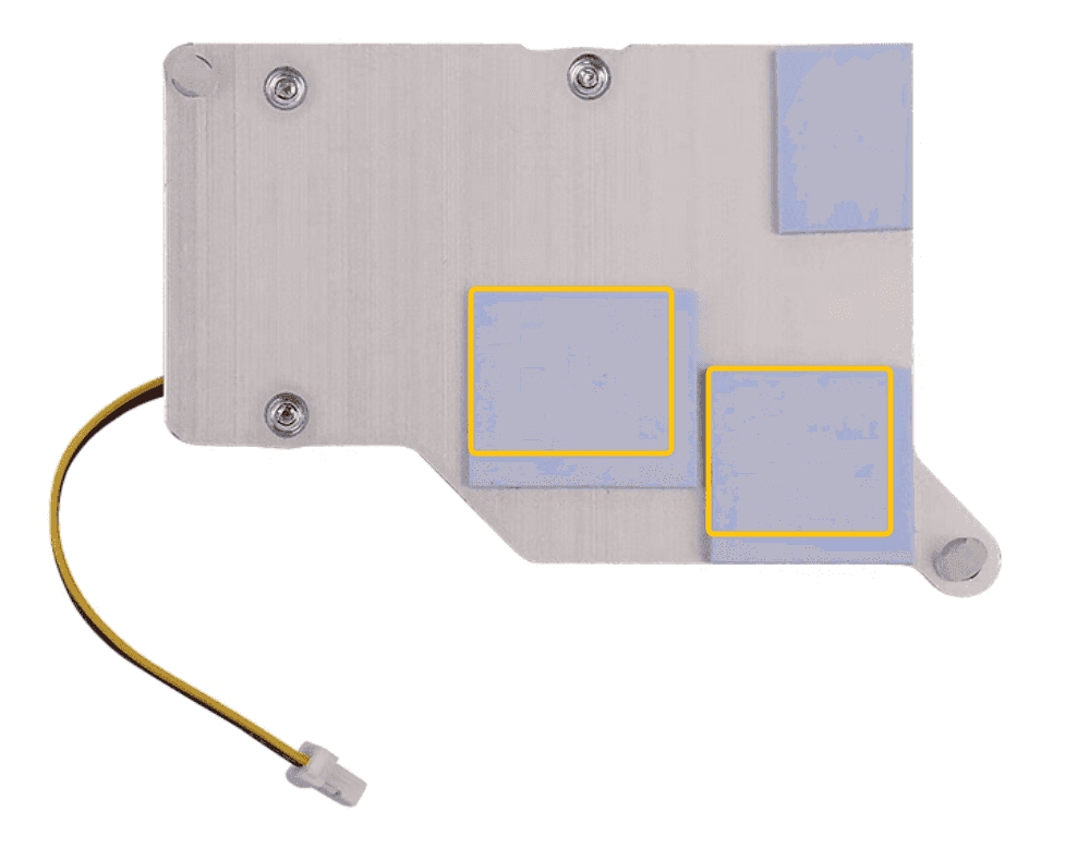
两块的表面尺寸约为14*12mm和13*11.5mm。
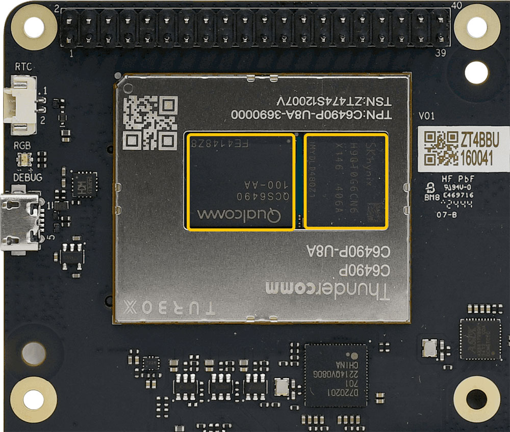
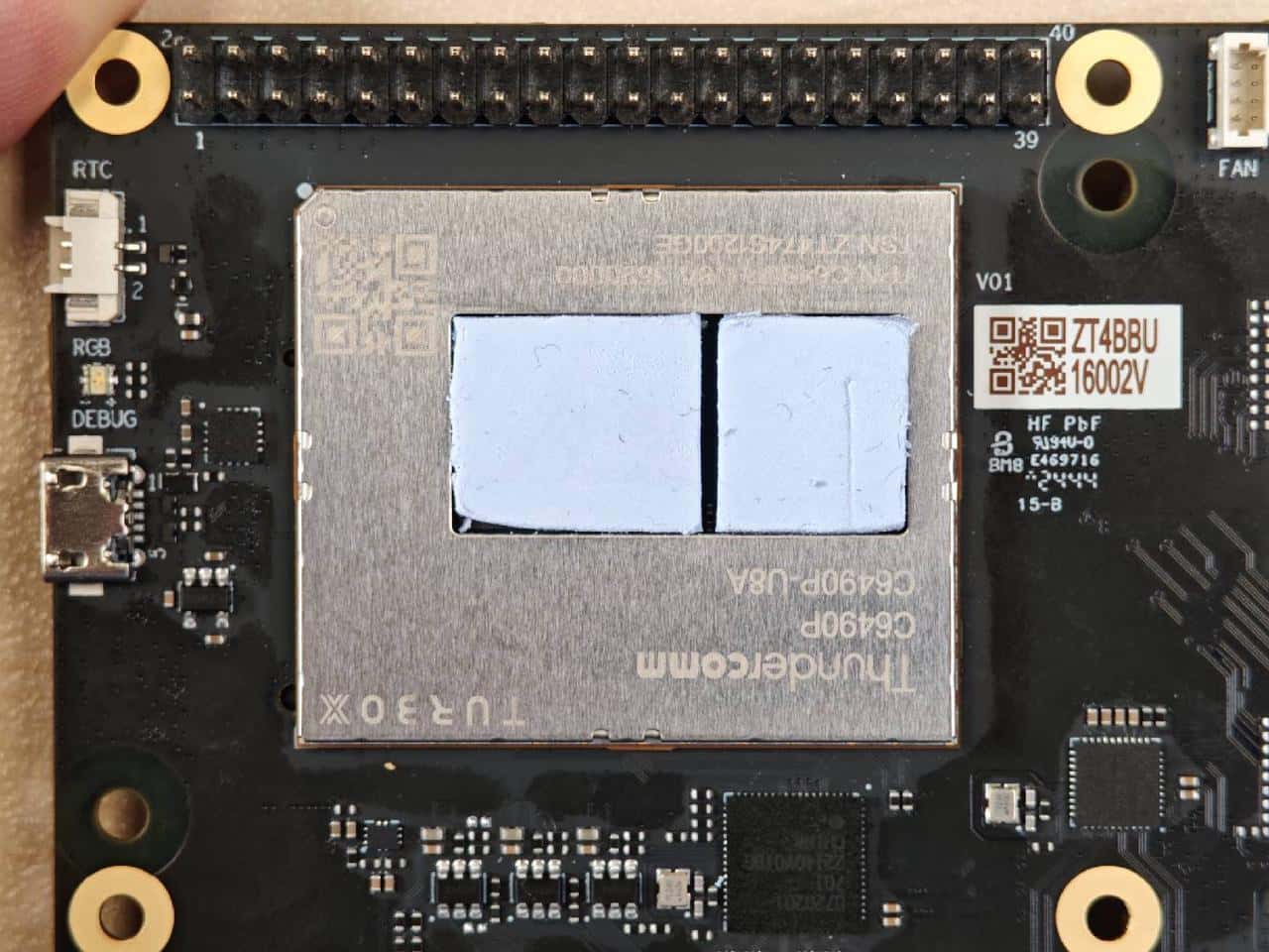
2.将裁剪好的两块导热硅脂贴在 RUBIK Pi 3 上对应位置。
 3. 安装散热器。
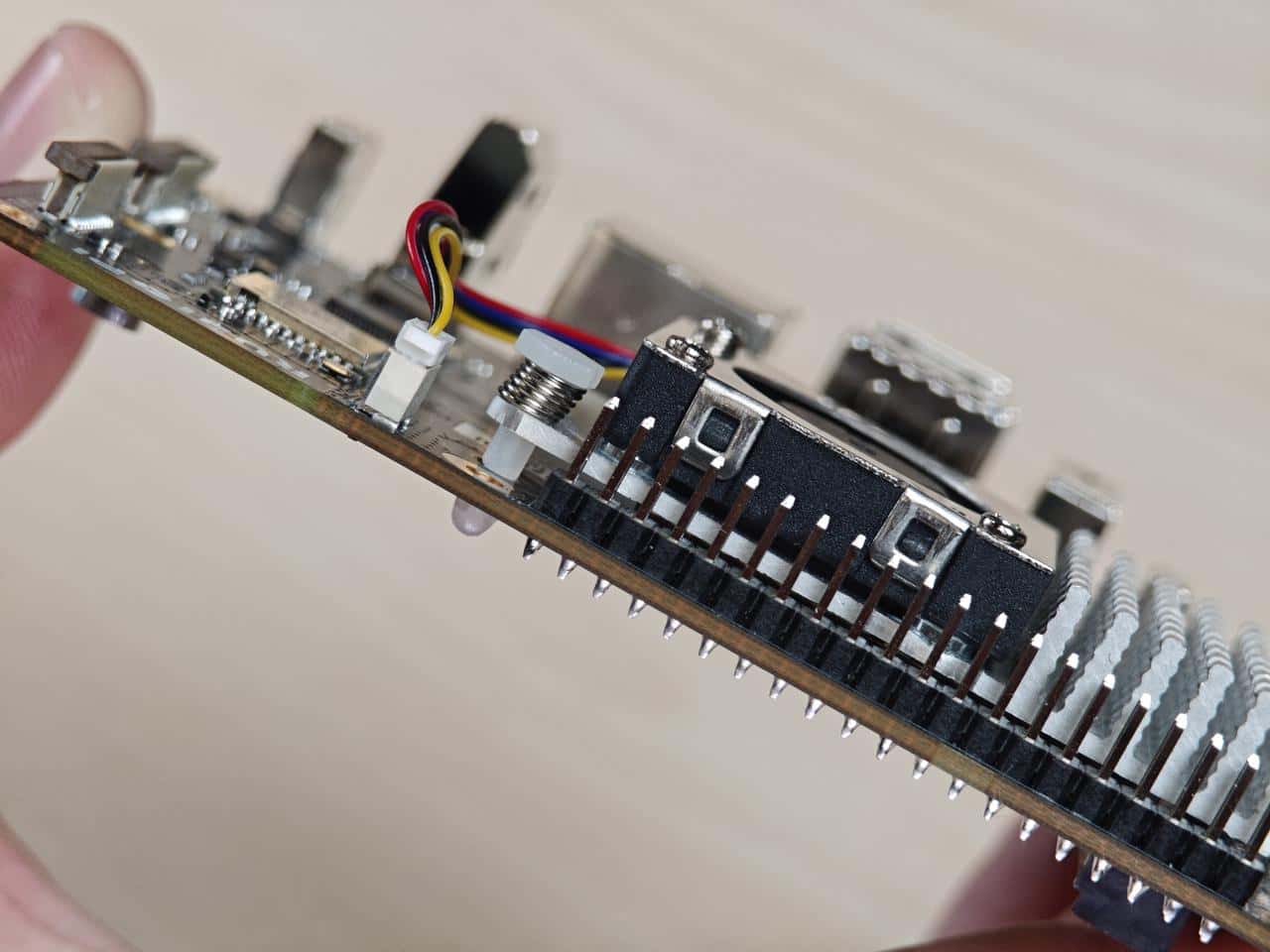
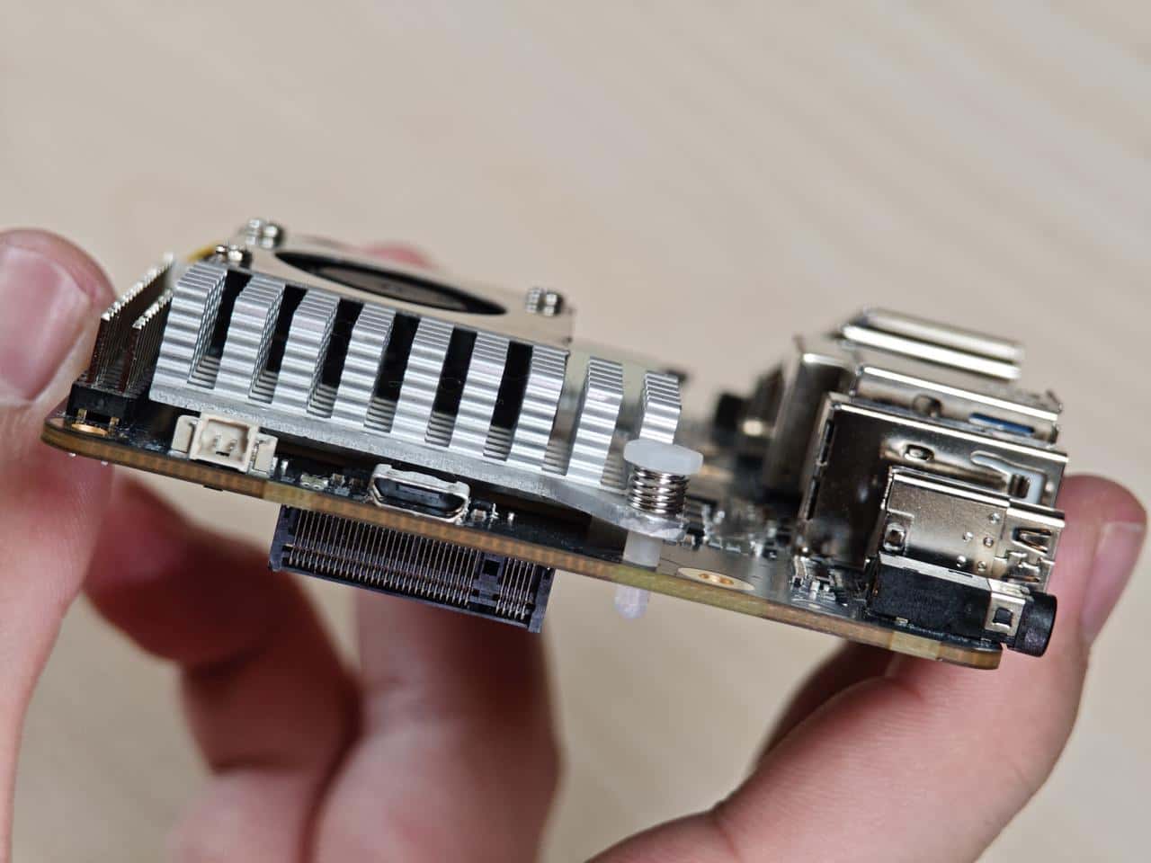
4.连接风扇排线。
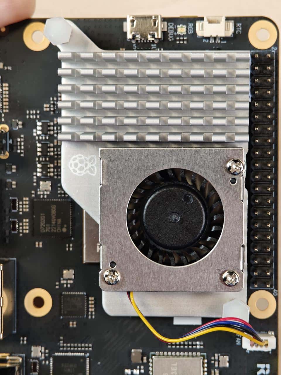
建议将风扇安装到 RUBIK Pi 3 上后不要将其取下。拆卸会导致风扇的推针和散热垫退化,并可能导致产品损坏。如果推针损坏或变形,或无法牢固夹住,请停止使用风扇。
2.8.2 风扇控制方法
RUBIK Pi 3 风扇会根据当前的 CPU 温度自动调整转速,同时也可使用下面命令进行手动控制转速,0和255分别表示风扇的最高和最低速度。
echo 100 >  /sys/class/hwmon/hwmon29/pwm1
echo 255 >  /sys/class/hwmon/hwmon29/pwm1
echo 0 >  /sys/class/hwmon/hwmon29/pwm1
2.9 以太网
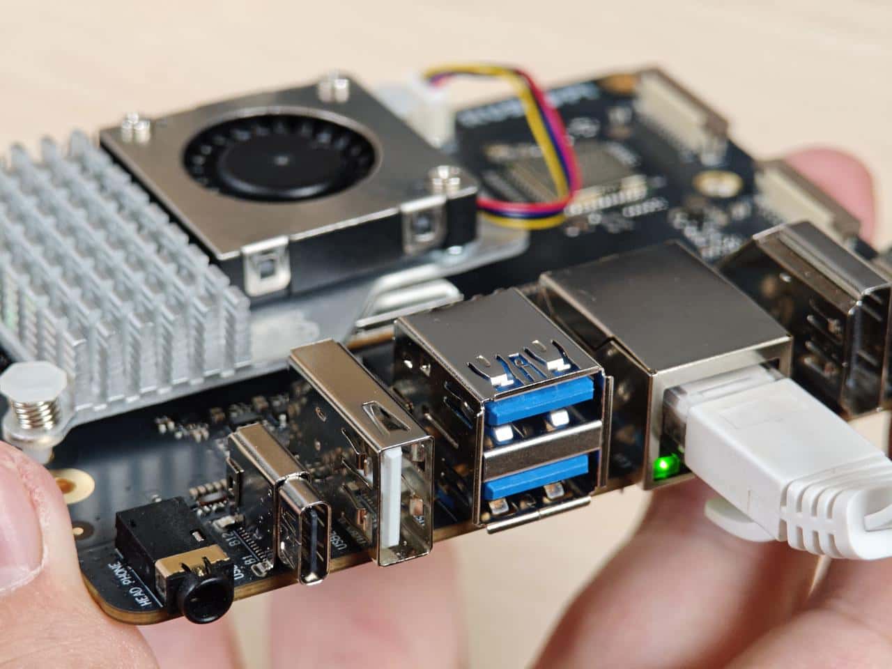
以太网接口为下图8, RUBIK Pi 3 支持千兆以太网:
接入网线,如下图所示:
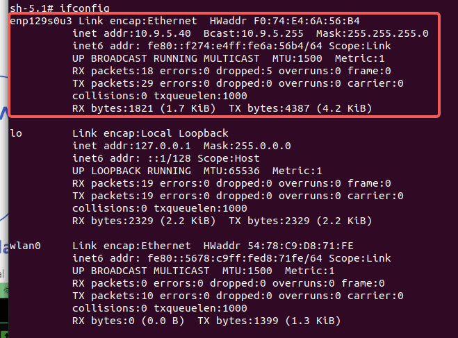
可在 RUBIK Pi 3 中使用下面命令查看网络连接情况,如下图所示,已经成功分配 IP,说明网络连接成功:
2.10 RTC电池接口
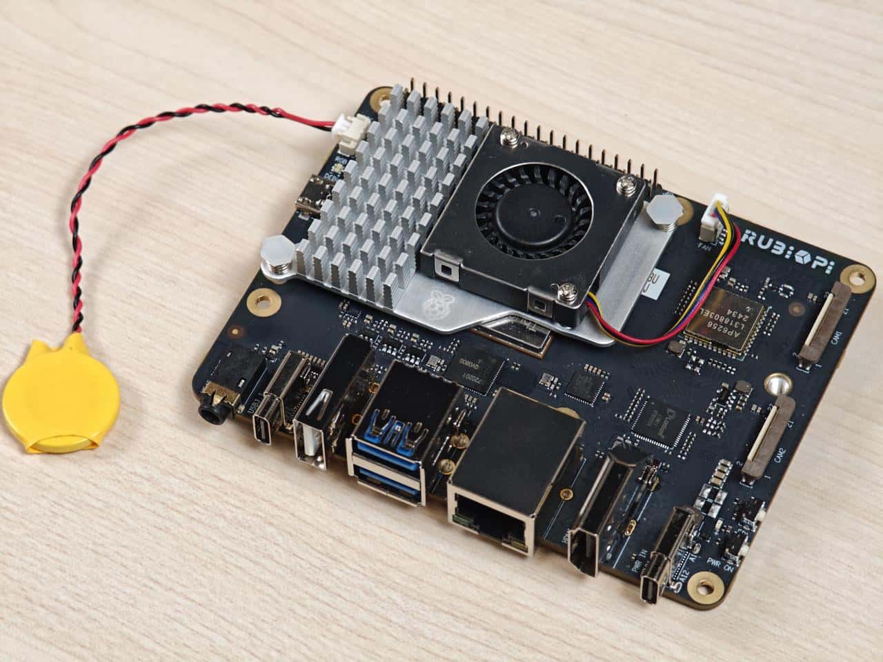
RTC(Real_Time Clock) 电池接口为下图1。

接入 RTC 电池, 如下图所示,并将时间写入 RUBIK Pi 3 的系统硬件时钟,可在 RUBIK Pi 3 完全断电后,仍对 RUBIK Pi 3 的系统时间进行保存。
在 RUBIK Pi 3 中将系统时间写入系统硬件时钟方法如下:
date -s "08:00:00 20241201" # 将系统时间设置为2024年12月1日8时0分
hwclock -w # 将系统时间写入系统硬件时钟
2.11 M.2 Key M 接口
M.2 Key M 接口为下图18:
M.2 Key M 接口可以接入规格为2280的固态硬盘,如下图所示:
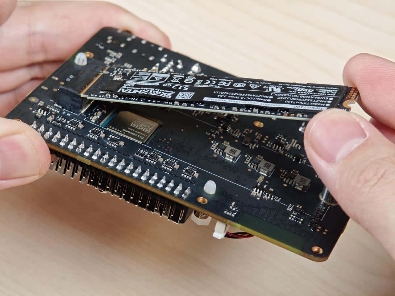

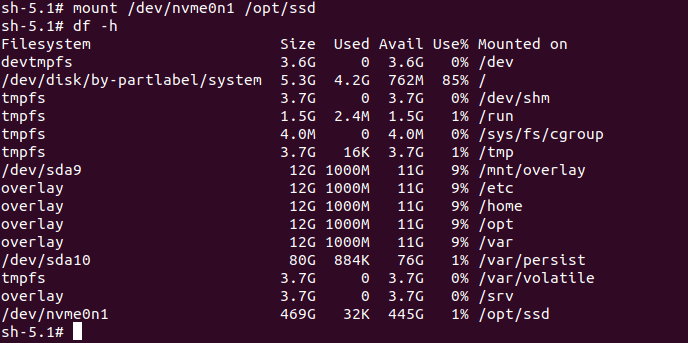
目前 RUBIK Pi 3暂未支持固态硬盘的自动挂载,可在 RUBIK Pi 3 中执行下面命令对固态硬盘手动挂载
mkdir /opt/ssd
mount /dev/nvme0n1 /opt/ssd
